Waukesha VHP Engine Controls: Difference between revisions
(→AFRC) |
|||
| (14 intermediate revisions by the same user not shown) | |||
| Line 2: | Line 2: | ||
EMIT engine control products (AFRC, Ignition, and speed controller) can be used on Waukesha VHP engines of various types. These kits can replace the ESM or upgrade older engines. This page covers ordering, install, and operating information. | EMIT engine control products (AFRC, Ignition, and speed controller) can be used on Waukesha VHP engines of various types. These kits can replace the ESM or upgrade older engines. This page covers ordering, install, and operating information. | ||
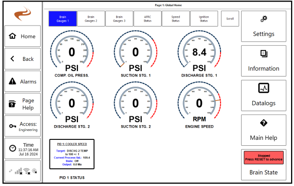
The engine control products and Brain (annunciator) can be used in any combination. Often all will be installed (Ignition, AFR, Speed, and Brain), but some other combination of modules or even a single module can be used. The home page will show any combo of modules that are currently attached as a new tab. | |||
[[File:Home 3.png|600px]] | |||
== Ordering Information == | == Ordering Information == | ||
| Line 41: | Line 45: | ||
|+ | |+ | ||
|- | |- | ||
! Application | ! Application !! Kit item number !! ICM Module (in kit) !! 13242 3" MPU to circular conn !! 15654-0400 4' MPU cable f/ long MPU !! 15654-1200 12' MPU cable f/ long MPU !! 15654-2000 20' MPU cable f/ long MPU !! 13241 5/8" Threaded hall sensor !! 15628-0800 Threaded hall harness 8' !! 15628- 1000 Threaded hall harness 10' !! 15633- 0251 ICM Power / Comm harness 25' !! 15633-0501 ICM Power / Comm harness 50' !! 14330-0002 Flanged coil !! 14305-0003 7044 ICM mount !! 65300-6005 3524 Mount kit !! 15652-0001 Wauk coil rail !! 15653-0001 ICM - 2x Rail Harness !! 15653-0002 ICM - 1x Rail Harness !! 15651-0181 Coil rail pigtail | ||
|- | |- | ||
| '''7044, 5794''' | | '''7044, 5794''' || '''20014-0045''' || 20270-0003 || 1 || 0 || 0 || 1 || 1 || 1 || 0 || 0 || 1 || 12 || 1 || 0 || 2 || 1 || 0 || 12 | ||
|- | |- | ||
| '''3524''' | | '''3524''' || '''20014-0046''' || 20270-0002 || 1 || 0 || 1 || 0 || 1 || 1 || 0 || 0 || 1 || 6 || 0 || 1 || 1 || 0 || 1 || 6 | ||
|} | |} | ||
'''Optional Components''' | '''Optional Components''' | ||
{| class="wikitable" style="margin:auto" | {| class="wikitable" style="margin-left: 0px; margin-right: auto;" | ||
|+ | |+ | ||
|- | |- | ||
| Line 62: | Line 66: | ||
=== Speed Module === | === Speed Module === | ||
'''Main Kits''' | |||
Note that the module is not part of the kit since it will usually be in the panel | |||
{| class="wikitable" style="margin:auto" | |||
|+ | |||
|- | |||
! Application !! Kit Item number !! 15550-0002 10 pin 50' servo- motor harness !! 17009-0003 Servo motor (heinzmann), linkage, bracket, mount | |||
|- | |||
| '''ESM Conversion, keep existing servo''' || '''20019-0001''' || 1 || 0 | |||
|- | |||
| '''ESM conversion, servo replaced, or servo needs to be added''' || '''20019-0002''' || 1 || 1 | |||
|} | |||
'''Optional Components''' | |||
{| class="wikitable" style="margin-left: 0px; margin-right: auto;" | |||
|+ | |||
|- | |||
! Item number !! Description !! Notes | |||
|- | |||
| 20310 || Speed module || Usually included in panel BOM | |||
|- | |||
| 13243 || Long 3" Mag Pickup to WP connector || Add qty 1 if engine will not have EMIT ignition | |||
|- | |||
| 15576 || Mag pickup harness, 50' || Add qty 1 if engine will not have EMIT ignition | |||
|} | |||
== Install Information == | |||
The Install guide can be found here: [https://drive.google.com/file/d/15AF34xpGOEOs7fFE_MFCZDX2EHeY7kAX/view?usp=sharing] | |||
== Pinout Reference == | |||
===Ignition Coils=== | |||
'''12 Cylinder Engines''' | |||
{| class="wikitable" style="margin-left: 0px; margin-right: auto;" | |||
|+ | |||
|- | |||
! Fire Order !! Cylinder Name !! ICM Board Pin !! ICM Box Coil Connector Pin !! Left Rail connector pin !! Right Rail connector pin | |||
|- | |||
| 1 || '''1R''' || J2,1 || J || || A | |||
|- | |||
| 2 || '''6L''' || J1,7 || F || F || | |||
|- | |||
| 3 || '''5R''' || J2,6 || N || || E | |||
|- | |||
| 4 || '''2L''' || J1,2 || B || B || | |||
|- | |||
| 5 || '''3R''' || J2,3 || L || || C | |||
|- | |||
| 6 || '''4L''' || J1,4 || D || D || | |||
|- | |||
| 7 || '''6R''' || J2,7 || P || || F | |||
|- | |||
| 8 || '''1L''' || J1,1 || A || A || | |||
|- | |||
| 9 || '''2R''' || J2,2 || K || || B | |||
|- | |||
| 10 || '''5L''' || J1,6 || E || E || | |||
|- | |||
| 11 || '''4R''' || J2,4 || M || || D | |||
|- | |||
| 12 || '''3L''' || J1,3 || C || C || | |||
|- | |||
| POWER || POWER || J1,5 and J2,5 || T || I || I | |||
|} | |||
'''6 Cylinder Engines''' | |||
{| class="wikitable" style="margin-left: 0px; margin-right: auto;" | |||
|+ | |||
|- | |||
! Fire Order !! Cylinder Name !! ICM Board Pin !! ICM Box Coil Connector Pin !! Rail connector pin | |||
|- | |||
| 1 || '''1''' || J1,1 || A || A | |||
|- | |||
| 2 || '''5''' || J1,6 || E || E | |||
|- | |||
| 3 || '''3''' || J1,3 || C || C | |||
|- | |||
| 4 || '''6''' || J1,4 || D || D | |||
|- | |||
| 5 || '''2''' || J1,2 || B || B | |||
|- | |||
| 6 || '''4''' || J1,7 || F || F | |||
|- | |||
| POWER || POWER || J1,5 || T || I | |||
|} | |||
===Throttle Actuator=== | |||
{| class="wikitable" style="margin-left: 0px; margin-right: auto;" | |||
|+ | |||
|- | |||
! Servo Connector Pin !! Harness Wire Color !! Panel Destination | |||
|- | |||
| A || White || Batt + | |||
|- | |||
| B || Shield or Yellow* || Ground | |||
|- | |||
| C || Green || Speed Pin 26 "Anlg out" | |||
|- | |||
| H || Black || Batt - | |||
|- | |||
| I || Red || Speed Pin 20 "TB Pos 1" | |||
|- | |||
| J || Shield* || Ground | |||
|} | |||
<nowiki>*</nowiki>Early harnesses had shield route to B, while later harnesses have shield route to J with Yellow routing to B. In either case, shield should always go to ground and yellow (if present) will go to ground. | |||
Note that a 182 ohm resistor should be installed between pin 20 and 23 of the speed/governor module. | |||
===Hall Sensor=== | |||
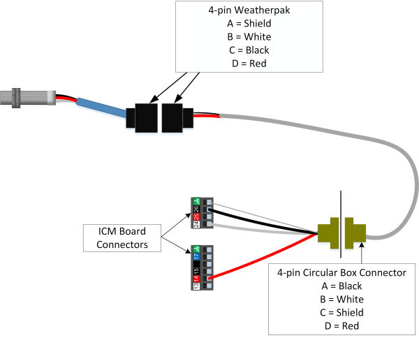
The diagram below shows the hall sensor wiring. Note that pin 14 supplies 12v to the red wire, and the white wire will have a weak pullup to 5v supplied by pin 24. | |||
[[File:Icm hall threaded.png|600px]] | |||
===Flywheel MPU=== | |||
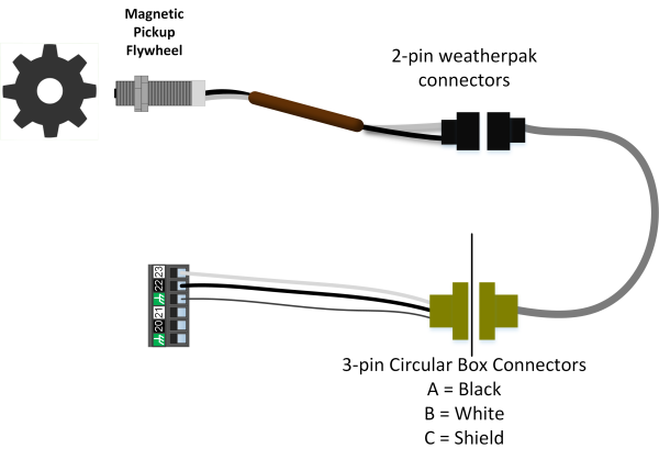
The Flywheel MPU wiring diagram is shown below. | |||
[[File:Icm mpu.png|600px]] | |||
Latest revision as of 16:56, 5 September 2024
Overview
EMIT engine control products (AFRC, Ignition, and speed controller) can be used on Waukesha VHP engines of various types. These kits can replace the ESM or upgrade older engines. This page covers ordering, install, and operating information.
The engine control products and Brain (annunciator) can be used in any combination. Often all will be installed (Ignition, AFR, Speed, and Brain), but some other combination of modules or even a single module can be used. The home page will show any combo of modules that are currently attached as a new tab.
Ordering Information
The sections below show what AFRC, Ignition, and governor kit would be selected for different applications, and the item numbers for spare parts.
AFRC
Note that the kit item number includes all items on that row except the module, which usually is already in the panel.
| Application | AFRC Module (Not in kit) | Kit Item Number | 13009 Narrowband O2 Sensor | 15075 Narrowband 50' harness | 15077 Narrowband 100' harness | 13019 Wideband O2 Sensor | 15508 Wideband 50' harness | 12016 1.5" inline flat pintle valve | 12112 1.5" inline radius valve | 15074 DPV harness 50' | 15076 DPV harness, 100' | 13001 25' TC | 13000 50' TC | 13035 100' TC | 13020 O2 Sensor Weldment | 13207 Manifold Pressure sensor | 15500 Manifold Pr harness, 25' | 15501 Manifold Pr harness, 50' | 14072-0002 CS800 regulator kit |
|---|---|---|---|---|---|---|---|---|---|---|---|---|---|---|---|---|---|---|---|
| 7042, 5792 GL (Fisher 99) | 20235 | 20011-0317 | 3 | 2 | 1 | 0 | 0 | 0 | 2 | 2 | 0 | 0 | 0 | 2 | 3 | 2 | 0 | 2 | 0 |
| F3524 GL (Fisher 99) | 20360 | 20011-0318 | 2 | 1 | 1 | 0 | 0 | 0 | 1 | 1 | 0 | 0 | 0 | 2 | 2 | 1 | 0 | 1 | 0 |
| F3524G (Mooney) | 20360 | 20011-0319 | 2 | 1 | 1 | 0 | 0 | 0 | 1 | 1 | 0 | 0 | 0 | 2 | 2 | 1 | 0 | 1 | 1 |
| 704x, 579x (Mooney) | 20235 | 20011-0320 | 3 | 2 | 1 | 0 | 0 | 0 | 2 | 2 | 0 | 0 | 0 | 2 | 3 | 2 | 0 | 2 | 2 |
| 7044, 5794 GSI (Fisher 99) | 20235 | 20011-0321 | 3 | 2 | 1 | 0 | 0 | 2 | 0 | 2 | 0 | 0 | 0 | 2 | 3 | 2 | 0 | 2 | 0 |
| F3524 GSI (Fisher 99) | 20360 | 20011-0322 | 2 | 1 | 1 | 0 | 0 | 1 | 0 | 1 | 0 | 0 | 0 | 2 | 2 | 1 | 0 | 1 | 0 |
| 704x, 579x GL Leanburn | 20230 | 20011-0323 | 0 | 0 | 0 | 2 | 2 | 0 | 2 | 2 | 0 | 0 | 0 | 2 | 3 | 2 | 0 | 2 | 0 |
| 3521 GL Leanburn | 20230 | 20011-0324 | 0 | 0 | 0 | 1 | 1 | 0 | 1 | 1 | 0 | 0 | 0 | 2 | 2 | 1 | 0 | 1 | 0 |
Ignition
Main Kits
| Application | Kit item number | ICM Module (in kit) | 13242 3" MPU to circular conn | 15654-0400 4' MPU cable f/ long MPU | 15654-1200 12' MPU cable f/ long MPU | 15654-2000 20' MPU cable f/ long MPU | 13241 5/8" Threaded hall sensor | 15628-0800 Threaded hall harness 8' | 15628- 1000 Threaded hall harness 10' | 15633- 0251 ICM Power / Comm harness 25' | 15633-0501 ICM Power / Comm harness 50' | 14330-0002 Flanged coil | 14305-0003 7044 ICM mount | 65300-6005 3524 Mount kit | 15652-0001 Wauk coil rail | 15653-0001 ICM - 2x Rail Harness | 15653-0002 ICM - 1x Rail Harness | 15651-0181 Coil rail pigtail |
|---|---|---|---|---|---|---|---|---|---|---|---|---|---|---|---|---|---|---|
| 7044, 5794 | 20014-0045 | 20270-0003 | 1 | 0 | 0 | 1 | 1 | 1 | 0 | 0 | 1 | 12 | 1 | 0 | 2 | 1 | 0 | 12 |
| 3524 | 20014-0046 | 20270-0002 | 1 | 0 | 1 | 0 | 1 | 1 | 0 | 0 | 1 | 6 | 0 | 1 | 1 | 0 | 1 | 6 |
Optional Components
| Item Number | Description | Note |
|---|---|---|
| 14331-0009 | Spark plug, Waukesha | |
| 14332-0004 | Plug extension | One per cylinder, connects coil to spark plug under valve cover |
Speed Module
Main Kits
Note that the module is not part of the kit since it will usually be in the panel
| Application | Kit Item number | 15550-0002 10 pin 50' servo- motor harness | 17009-0003 Servo motor (heinzmann), linkage, bracket, mount |
|---|---|---|---|
| ESM Conversion, keep existing servo | 20019-0001 | 1 | 0 |
| ESM conversion, servo replaced, or servo needs to be added | 20019-0002 | 1 | 1 |
Optional Components
| Item number | Description | Notes |
|---|---|---|
| 20310 | Speed module | Usually included in panel BOM |
| 13243 | Long 3" Mag Pickup to WP connector | Add qty 1 if engine will not have EMIT ignition |
| 15576 | Mag pickup harness, 50' | Add qty 1 if engine will not have EMIT ignition |
Install Information
The Install guide can be found here: [1]
Pinout Reference
Ignition Coils
12 Cylinder Engines
| Fire Order | Cylinder Name | ICM Board Pin | ICM Box Coil Connector Pin | Left Rail connector pin | Right Rail connector pin |
|---|---|---|---|---|---|
| 1 | 1R | J2,1 | J | A | |
| 2 | 6L | J1,7 | F | F | |
| 3 | 5R | J2,6 | N | E | |
| 4 | 2L | J1,2 | B | B | |
| 5 | 3R | J2,3 | L | C | |
| 6 | 4L | J1,4 | D | D | |
| 7 | 6R | J2,7 | P | F | |
| 8 | 1L | J1,1 | A | A | |
| 9 | 2R | J2,2 | K | B | |
| 10 | 5L | J1,6 | E | E | |
| 11 | 4R | J2,4 | M | D | |
| 12 | 3L | J1,3 | C | C | |
| POWER | POWER | J1,5 and J2,5 | T | I | I |
6 Cylinder Engines
| Fire Order | Cylinder Name | ICM Board Pin | ICM Box Coil Connector Pin | Rail connector pin |
|---|---|---|---|---|
| 1 | 1 | J1,1 | A | A |
| 2 | 5 | J1,6 | E | E |
| 3 | 3 | J1,3 | C | C |
| 4 | 6 | J1,4 | D | D |
| 5 | 2 | J1,2 | B | B |
| 6 | 4 | J1,7 | F | F |
| POWER | POWER | J1,5 | T | I |
Throttle Actuator
| Servo Connector Pin | Harness Wire Color | Panel Destination |
|---|---|---|
| A | White | Batt + |
| B | Shield or Yellow* | Ground |
| C | Green | Speed Pin 26 "Anlg out" |
| H | Black | Batt - |
| I | Red | Speed Pin 20 "TB Pos 1" |
| J | Shield* | Ground |
*Early harnesses had shield route to B, while later harnesses have shield route to J with Yellow routing to B. In either case, shield should always go to ground and yellow (if present) will go to ground.
Note that a 182 ohm resistor should be installed between pin 20 and 23 of the speed/governor module.
Hall Sensor
The diagram below shows the hall sensor wiring. Note that pin 14 supplies 12v to the red wire, and the white wire will have a weak pullup to 5v supplied by pin 24.
Flywheel MPU
The Flywheel MPU wiring diagram is shown below.


