|
|
| (15 intermediate revisions by 2 users not shown) |
| Line 1: |
Line 1: |
| | See the bottom part of this page for a general overview, or the articles below for specific topics. |
| | |
| ==EDR Documents and Guides== | | ==EDR Documents and Guides== |
|
| |
|
| [[Config Tool]]
| | === Main Guides === |
| | |
| [[Field Configuration]]
| |
| | |
| [[Installation Guides]]
| |
| | |
| [[Internal EDT Update]]
| |
| | |
| [[Troubleshooting Guide]]
| |
| | |
| [[Connecting]]
| |
| | |
| [[Wi-Fi Console Pages]]
| |
| | |
| == Overview == | |
| The EDR has a configuration and status page that can be viewed using a phone or computer by connecting to the device over WiFi. This console generally is used on installation to make sure data is collected correctly, or for debugging.
| |
| | |
| == Wi-Fi Console Pages ==
| |
| From the top right menu on a phone, or along the top on a computer, there will be the following page categories: Status, Compressor Master, Alerts, Engine Data Translator, Modbus Slave, and Debug. Each of these 6 pages are detailed below.
| |
| | |
| === Status ===
| |
| The Status page shows the current readings for engine and compressor data. Settings cannot be edited on this page. Also shown under “General” is the serial number and software version.
| |
| | |
| <nowiki>*</nowiki>Insert Images*
| |
| | |
| The Modbus master data will show the latest values read from the annunciator, and when the value was last read. Normally values are polled every 10 seconds, but this may vary by software version.
| |
| | |
| The engine data section of General Status will show any collected data from the engine data translator.
| |
|
| |
|
| === Compressor Master ===
| | [[EDR Manual]] |
| The Compressor Master page is used for viewing and changing information related to the Modbus master table. Sections are:
| |
|
| |
|
| Modbus Master Table
| | [[EDR Wi-Fi Console]] |
|
| |
|
| Under this heading is shown the full master table and raw values read.
| | [[EDR Installation Guide]] |
|
| |
|
| <nowiki>*</nowiki>Insert Image*
| | [[EDR Troubleshooting Guide]] |
|
| |
|
| In the above screenshot, Engine speed is being pulled from Register 41003, ID 10. The value is being read as “0” successfully, because the age is 7s.
| | === Minor Topics === |
|
| |
|
| Some values will have a ‘Never’ value for the Age because they have not yet been successfully read. In some cases, the value is never even expected because the register is “0”- For example, “Manifold Pressure Right” on a single bank unit will never be seen. If an expected value is missing, it can be debugged from this table.
| | [[Default Panel Settings for EDRs]] |
|
| |
|
| The table can be edited on this page by selecting a cell and changing the value.
| | [[EDR Software Update]] |
|
| |
|
| ==== Modbus Master Table File ====
| | [[EDR Field Configuration]] |
| The next heading on this page is “Modbus Master Table File”, where the entire master table can be downloaded or uploaded.
| |
|
| |
|
| <nowiki>*</nowiki>Insert Image*
| | [[EDR Config Tool]] |
|
| |
|
| On initial setup, it may be easier to edit the file to get all the registers entered at once rather than edit each row individually over the Wi-Fi console. Also, the download/upload function can be used to use a configuration on another unit.
| | [[EDR Internal EDT Update]] |
|
| |
|
| To download the current file, select “Download”. To upload a new file, select “Browse” then “Upload”.
| | [[Connecting EDR to EIM with Ethernet]] |
|
| |
|
| ==== Network Configuration ====
| | [[CAN Terminations With CAT Panel]] |
| The network configuration section is used to setup the RS-485 or Ethernet settings to connect to the slave device(s). Select either Serial or Ethernet by selecting a checkbox, then enter the information to match the settings for the device being targeted.
| |
|
| |
|
| ==== Network Statistics ====
| | [[EDR Port Timings]] |
| The network statistics section shows the number of bytes sent and received. This may be useful for debugging.
| |
|
| |
|
| ==== Recent Messages ====
| | [[EDR to 20240 Connection]] |
| This heading shows the latest message sent and received over RS-485. This may be useful for debugging.
| |
|
| |
|
| === Alerts ===
| | [[EDR Loopback Test]] |
|
| |
|
| ==== Current Run Register ==== | | == EDR Overview == |
| There is a target register and ID that the Data Relay uses to determine the current run status.
| |
|
| |
|
| The “Current Run Register” heading shows the current reading from that register and how it is decoded using the Run Status Table.
| | === Hardware and System Overview === |
|
| |
|
| Below the current reading/state, the configuration for the target ID/ register for the run status can be adjusted. Normally this should be set up only once.
| | The EMIT Data Relay (EDR) is a module for interfacing non-EMIT control system data to EMIT’s telematics platform. Non-EMIT systems include popular compressor control annunciators and engine control units. The EDR connects to these systems via MODBUS and propriety protocols, organizes the data, and transmits the data via cellular modem to a customer facing database for remote observation. |
|
| |
|
| ==== Current Fault Register ====
| | '''Power''' |
| Like the “Current Run Register”, the Current Fault Register section will show the latest reading from the fault register and how it is interpreted.
| |
|
| |
|
| In some cases, the fault code register might not have a valid value if the unit is not actually faulted.
| | *12 – 30VDC power supply input range |
| | *Maximum power consumption: 30W |
|
| |
|
| The current ID / Register being polled for the fault status can also be edited here if needed.
| | '''Environmental''' |
|
| |
|
| ==== Run Status Table ====
| | *Temperature: -40°C to +65°C (-40°F to 149°F) T4 |
| The Run Status Table section shows the entire run status table configured. The value/ state type pairs can be adjusted here if needed. When the Data Relay reads the run status register, it will use this table to interpret the current state of the annunciator.
| | *Humidity: 5% - 90%, non-condensing |
|
| |
|
| ==== Fault Code Table ====
| | '''Communication''' |
| Under the Fault Code Table section, the entire fault code table is shown. The table can be edited or expanded here if needed.
| |
|
| |
|
| ==== Table Configuration Files ====
| | *USB host for future use |
| Under this section, the fault code table or the run status table can be downloaded / uploaded to the computer for editing in Excel ®. This is often the fastest way to set up the tables on initial setup.
| | *RS-485 half-duplex MODBUS RTU Master for panel annunciator communication |
| | *RS-485 half-duplex MODBUS RTU Slave for spare or expansion |
| | *Ethernet port for Modbus/TCP access, both master and slave |
| | *ECU J1708 and ECU CAN for Caterpillar ADEM access |
| | *Wi-Fi Antenna for local wireless access to unit information |
| | *Cell module for remote data collection and callouts |
| | *GPS for location service & accurate time |
|
| |
|
| === Engine Data Translator === | | === General System Concepts === |
| The Engine Data Translator tab has two sections related to the engine data.
| |
|
| |
|
| ==== Engine Data ====
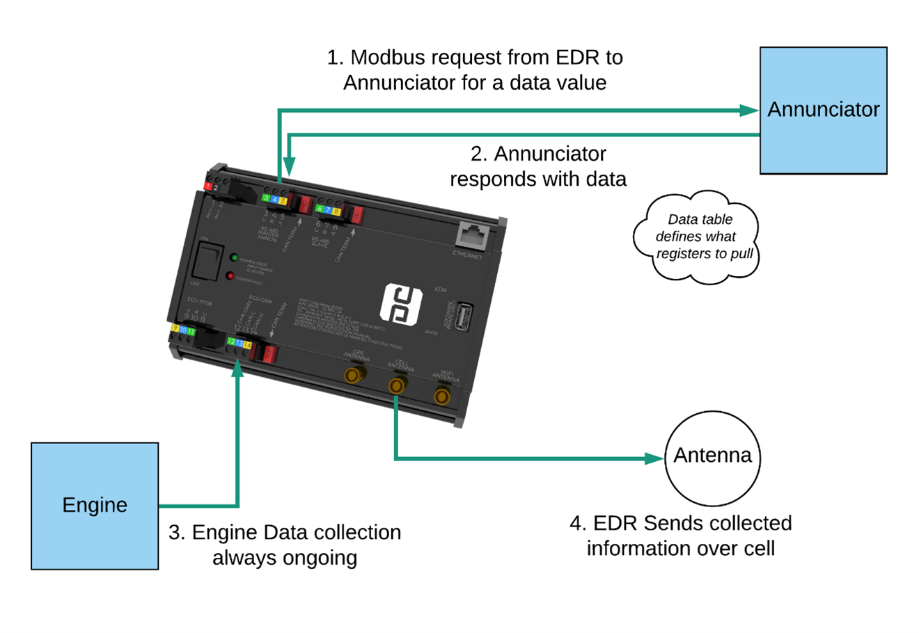
| | In the most typical use case, the Data Relay acts as a “Modbus Master” to a non-EMIT panel system. Using some defined data tables, the Data Relay will request data values such as suction pressure, oil temp, etc., from the panel system via RS-485 Modbus or Modbus/TCP. |
| This section will show all currently collected engine data. Any valid information seen on the engine data bus will show up here.
| |
|
| |
|
| ==== Configuration ====
| | [[File:Edr-concept-diagram.png]] |
| Under this section, the engine type can be selected.
| |
|
| |
|
| === Modbus Slave ===
| | Each Modbus data value is configured by specifying a target Register and Slave ID of the source of the information (typically the panel annunciator). For example, the suction pressure might be present at Slave ID 10, Register 41001. The Data Relay will request for Register 41001 from Slave ID 10, the annunciator will respond with the data, and the Data Relay will store this response as “Suction Pressure”. |
| The Modbus Slave tab is used to set up the slave connection of the Data Relay. This is only used if another SCADA needs to pull engine data over Modbus from the Data Relay. This tab has three sections.
| |
|
| |
|
| ==== Network Configuration ====
| | This data is accumulated into standard blocks of information and then sent to EMIT Data Services via cell connection. This also includes run status information for the purposes of sending callouts. Additionally, the Data Relay will collect engine data from an engine control unit, such as Caterpillar ADEM ®, which will also be sent to the server. |
| The Network Configuration section is used to configure the serial or IP settings for the Data Relay. The slave ID of the Data Relay itself can also be set here.
| |
|
| |
|
| ==== Network Statistics ====
| | Separately, the Data Relay can operate as a Modbus Slave device. In this scenario, another SCADA system uses the Data Relay only for engine data translation. |
| This section shows the bytes sent and received by the RS-485 slave port. This information may be useful for debugging.
| |
|
| |
|
| ==== Modbus Table ==== | | ===Wiring=== |
| This section has a link to download the Modbus slave table. This table is the same for all devices.
| |
|
| |
|
| === Debug ===
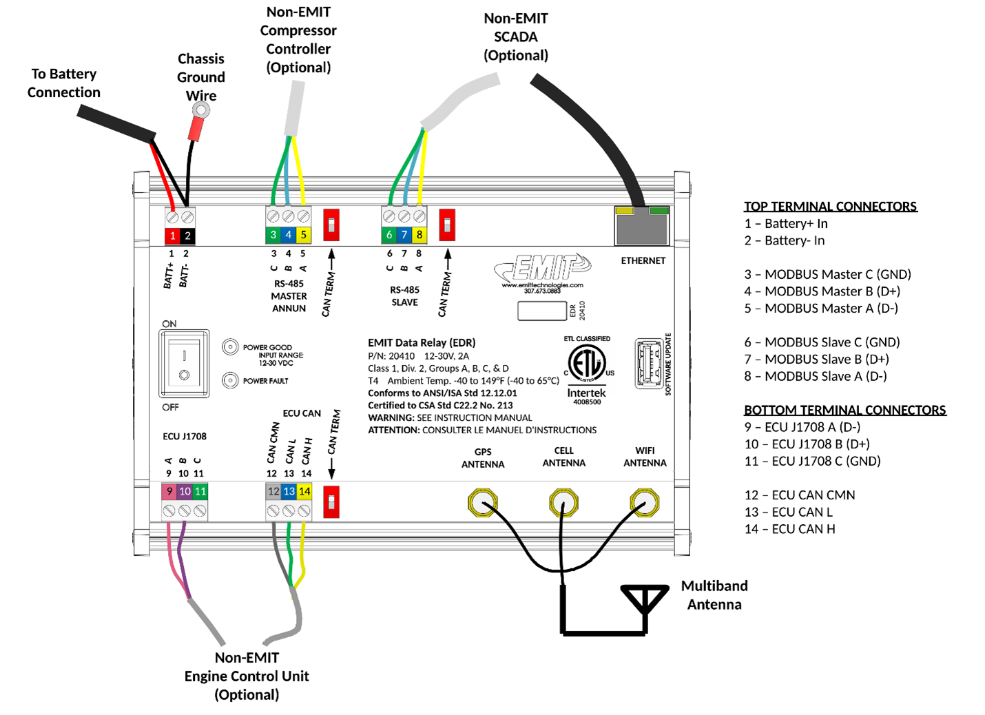
| | A general wiring diagram of all possible connections is shown below. In most cases some subset of these connections will be used. |
| The Debug tab has three sections related to the connection to EMIT Data Services and Debugging.
| |
|
| |
|
| ==== Device Config ====
| | [[File:Edr-wiring-full.png]] |
| This section shows the cellular config of the device.
| |
|
| |
|
| The “Service Level” will show 2 or higher if the unit is activated to send remote data to EMIT. The activation is done by calling 307-673-0883 and asking for “Telematics Activation” or emailing [[Mailto:telematics@emittechnologies.com|telematics@emittechnologies.com]] with the board serial number, and the activation is sent over the air. The Unit Number is also pulled from the remote server and can be configured in the portal at <nowiki>https://data.emittechnologies.com/</nowiki> .
| | ===Configuration=== |
|
| |
|
| The “Sync Telematics Config” button is not often used but may be requested by EMIT Tech support. The button will ping the server for the latest service level and Unit. If the Unit number is not correct, try this button.
| | There are three spreadsheet files that define how an EDR communicates with another panel. These are called the modbus master table, the run status table, and the fault code (or shutdown code) table. |
|
| |
|
| The “Send Test Callout” button can be used to send a test callout to the current callout targets for the unit.
| | These three files can be saved and loaded to different EDRs when the panels are the same. |
|
| |
|
| ==== Connection Information ====
| | Creating a new configuration is described in the page [[EDR Field Configuration]] |
| The connection information section shows current Cell connection info. If there is no signal strength or carrier shown here, check the antenna connections. In some cases, a higher antenna may be needed.
| |
|
| |
|
| ==== Software Update ====
| | Additionally parts of the tables can be edited through the wifi console. See [[EDR Wi-Fi Console]] |
| The software update section is used to upload a software update. Select “Browse” to select a file, then “Update” to start an update. The update process will take about a minute. Software updates will have a file name “EDR_update[…].emt” where the […] varies.
| |
See the bottom part of this page for a general overview, or the articles below for specific topics.
EDR Documents and Guides
Main Guides
EDR Manual
EDR Wi-Fi Console
EDR Installation Guide
EDR Troubleshooting Guide
Minor Topics
Default Panel Settings for EDRs
EDR Software Update
EDR Field Configuration
EDR Config Tool
EDR Internal EDT Update
Connecting EDR to EIM with Ethernet
CAN Terminations With CAT Panel
EDR Port Timings
EDR to 20240 Connection
EDR Loopback Test
EDR Overview
Hardware and System Overview
The EMIT Data Relay (EDR) is a module for interfacing non-EMIT control system data to EMIT’s telematics platform. Non-EMIT systems include popular compressor control annunciators and engine control units. The EDR connects to these systems via MODBUS and propriety protocols, organizes the data, and transmits the data via cellular modem to a customer facing database for remote observation.
Power
- 12 – 30VDC power supply input range
- Maximum power consumption: 30W
Environmental
- Temperature: -40°C to +65°C (-40°F to 149°F) T4
- Humidity: 5% - 90%, non-condensing
Communication
- USB host for future use
- RS-485 half-duplex MODBUS RTU Master for panel annunciator communication
- RS-485 half-duplex MODBUS RTU Slave for spare or expansion
- Ethernet port for Modbus/TCP access, both master and slave
- ECU J1708 and ECU CAN for Caterpillar ADEM access
- Wi-Fi Antenna for local wireless access to unit information
- Cell module for remote data collection and callouts
- GPS for location service & accurate time
General System Concepts
In the most typical use case, the Data Relay acts as a “Modbus Master” to a non-EMIT panel system. Using some defined data tables, the Data Relay will request data values such as suction pressure, oil temp, etc., from the panel system via RS-485 Modbus or Modbus/TCP.
Each Modbus data value is configured by specifying a target Register and Slave ID of the source of the information (typically the panel annunciator). For example, the suction pressure might be present at Slave ID 10, Register 41001. The Data Relay will request for Register 41001 from Slave ID 10, the annunciator will respond with the data, and the Data Relay will store this response as “Suction Pressure”.
This data is accumulated into standard blocks of information and then sent to EMIT Data Services via cell connection. This also includes run status information for the purposes of sending callouts. Additionally, the Data Relay will collect engine data from an engine control unit, such as Caterpillar ADEM ®, which will also be sent to the server.
Separately, the Data Relay can operate as a Modbus Slave device. In this scenario, another SCADA system uses the Data Relay only for engine data translation.
Wiring
A general wiring diagram of all possible connections is shown below. In most cases some subset of these connections will be used.
Configuration
There are three spreadsheet files that define how an EDR communicates with another panel. These are called the modbus master table, the run status table, and the fault code (or shutdown code) table.
These three files can be saved and loaded to different EDRs when the panels are the same.
Creating a new configuration is described in the page EDR Field Configuration
Additionally parts of the tables can be edited through the wifi console. See EDR Wi-Fi Console


