AFRC Setup: Difference between revisions
Sean Sanders (talk | contribs) |
|||
| (5 intermediate revisions by 2 users not shown) | |||
| Line 1: | Line 1: | ||
Video available for this topic: https://www.youtube.com/watch?v=PAmjcq7CPt0 | Video available for this topic: https://www.youtube.com/watch?v=PAmjcq7CPt0 | ||
== | == Engine Condition == | ||
For proper AFRC operation, it is critical that the engine be in good operational status. Verify the following before running the AFRC: | For proper AFRC operation, it is critical that the engine be in good operational status. Verify the following before running the AFRC: | ||
| Line 11: | Line 11: | ||
* Ignition system functioning correctly and timing set appropriately for fuel composition | * Ignition system functioning correctly and timing set appropriately for fuel composition | ||
=== | === Preparing for start === | ||
While the engine is not running, perform the following steps to prepare the controller for operation: | While the engine is not running, perform the following steps to prepare the controller for operation: | ||
* | * AFRC module is installed and wired | ||
* Digital power valve(s) are installed | * Digital power valve(s) are installed | ||
* Run signal source is properly connected | * Run signal source is properly connected | ||
* Run signal source is properly selected on the Run Signal Trigger screen (Pg. 10) | * Run signal source is properly selected on the Run Signal Trigger screen (Pg. 10) | ||
* Fuel connections are secure and leak-free | * Fuel connections are secure and leak-free | ||
* Enter Setup or Engineering mode on the controller by entering the appropriate password | * Enter Setup or Engineering mode on the controller by entering the appropriate password | ||
* Set the “Control” | * Set the “Control” button on the AFRC Home screen to “Manual” | ||
The engine can now be started. | The engine can now be started. | ||
=== | == Main Setup == | ||
The main setup is under Settings - AFRC - Main Setup | |||
=== Engine Setup === | |||
[[File:AFRC Engineering Setup.jpg|600px]] | |||
*Bank count: Select 1 or 2 banks for the number of valves used | |||
*Engine type: Select the type of engine, richburn or leanburn | |||
*O2 sensor type: Select narrowband for 4-wire sensors that read mV, and wideband for 6-wire sensors that read lambda ratio. Note that leanburn engines must use wideband. | |||
=== Control Setup === | |||
[[File:AFRC Control Setup.jpg|600px]] | |||
==== Control type ==== | |||
The AFRC Advanced has the ability to switch between control types “Setpoint” and “Auto Control”. | |||
''Auto Control'' | |||
“Auto Control” is a patented control algorithm that uses both a pre-catalyst and post-catalyst O2 sensor to find the most appropriate target setpoint and maintains that setpoint through a variety of conditions. The target setpoint is not user adjustable and is managed by the AFRC Advanced without the need for any user input. “Auto Control” is only available for single bank and dual bank rich burn engine configurations. Multi-setpoint mapping is disabled while in this mode. | |||
If “Auto Control” is selected as the control type, options will be made available to adjust the software to target either for a richer or leaner setting using the “Lean” and “Rich” buttons on the Engineering Setup screen (Pg. 207). By default, this setting is configured for equal CO and NOx reduction with a rich/lean setting value of 50. Due to varying site conditions, including fuel gas and ignition timing, this value may require an initial adjustment after installation. If lower CO emissions are desired at the expense of higher NOx, the rich/lean setting can be reduced by selecting the “Lean” button to adjust rich/lean value less than 50. Similarly, if lower NOx emissions are desired at the expense of higher CO, the rich/lean setting can be increased by selecting the “Rich” button to adjust rich/lean value greater than 50. The rich/lean value’s range is 0 to 100, where 0 is the maximum lean value and 100 is the maximum rich value. | |||
When “Auto Control” is selected, an alarm is automatically generated on the Alarm Setup screen (Pg. 206) to switch to “Setpoint” control if the “Auto Control” setpoint drifts below 600 or above 800. If the alarm is triggered, it must be reset on the Alarms screen (Pg. 40) before “Auto Control” can be re-enabled. Typical cause of the drift outside of this range is an expired or ineffective Post-Cat O2 sensor. | |||
''Setpoint Control'' | |||
“Setpoint” control mode controls off of a user, or mapping table, defined setpoint that corresponds with the desired emissions reduction. If desired, multiple setpoints can be used to automatically change the target setpoint based on sensor readings through the AFRC’s mapping feature. | |||
==== Load Delay ==== | |||
The load delay setting adjusts the amount of time to delay the AFRC from taking control of the valve after it has detected a valid run signal and the sensors are warm. The intention of this configuration is to allow the engine to fully warm up and load before taking control. | |||
The default value is set to 30 seconds, but the delay can optionally be configured to 1 minute, 5 minutes, 10 minutes, or 20 minutes. | |||
==== Bank Sensitivity ==== | |||
The AFRC operates on a PID control loop to automatically adjust the valve to match the actual sensor reading to the target setpoint. By default, the control loop has been pre-tuned to find the target setpoint quickly while maintaining stability. If the condition exists where the valve needs to be either more or less responsive, the PID control loop can be adjusted by selecting the “Faster” or “Slower” buttons around the “Response Time” label. Slowing the valve response will decrease the sensitivity of the control loop, and increasing the valve response will increase the sensitivity of the control loop. The individual PID values are automatically adjusted based on the single “Response Time” value. The default “Response Time” value is 50 and is adjustable between 0 and 100. | |||
==== Autocontrol Rich/Lean ==== | |||
If using Autocontrol mode, this setting helps determine how the control settles based on catalyst response. The default is 50, and higher values will make the controller settle more rich. | |||
=== Sensor Setup === | |||
The AFRC Advanced has the following optional sensor inputs available for process monitoring, run signal, and mapping: | The AFRC Advanced has the following optional sensor inputs available for process monitoring, run signal, and mapping: | ||
* Manifold Pressure Sensors (two available) | *Manifold Pressure Sensors (two available) | ||
* | **Manifold Press Left" and "Manifold Press Right" | ||
*Single bank configurations utilize the "Manifold Pressure Left" input | **Single bank configurations utilize the "Manifold Pressure Left" input | ||
*Sensors are pre-configured for the system and can only be enabled or disabled | **Sensors are pre-configured for the system and can only be enabled or disabled | ||
*Analog (one available) | *Analog (one available) | ||
*"ANALOG" | **"ANALOG" | ||
*Configurable to 0-5V, 1-5V, or 4-20mA | **Configurable to 0-5V, 1-5V, or 4-20mA | ||
*Oil Pressure Switch (one available) | *Oil Pressure Switch (one available) | ||
*"Oil Press Switch" | **"Oil Press Switch" | ||
*Pre-configured as normally open (N/O) and can only be enabled or disabled | **Pre-configured as normally open (N/O) and can only be enabled or disabled | ||
*Thermistor (one available) | *Thermistor (one available) | ||
*"Ambient" | **"Ambient" | ||
*Thermocouple (one available) | *Thermocouple (one available) | ||
*"Manifold" | **"Manifold" | ||
*Type-K thermocouple only | **Type-K thermocouple only | ||
*Magnetic Pickup (one available) | *Magnetic Pickup (one available) | ||
*"RPM" | **"RPM" | ||
*1-100 Volts | **1-100 Volts | ||
These sensors are set up under the Main Setup of the AFRC. | |||
==== Configuring the Analog Input ==== | |||
For the general purpose “ANALOG” input, the following fields are required: | For the general purpose “ANALOG” input, go to the Sensor Setup slide of the AFRC main setup. The following fields are required: | ||
* Name – Label of the sensor that will be displayed within the AFRC’s user interface | * Name – Label of the sensor that will be displayed within the AFRC’s user interface | ||
* | * Units – Units of the sensor | ||
* | * Type – 4-20mA, 0-5 Volt, or 1-5V sensor output type | ||
* Low Scale – Lowest output value of the sensor | * Low Scale – Lowest output value of the sensor | ||
* Full Scale – Highest output value of the sensor | * Full Scale – Highest output value of the sensor | ||
==== Configuring RPM ==== | |||
The RPM input is configured by providing the pulses per revolution. | |||
=== | === Run Signal and Valve Home === | ||
=== | ==== Run Signal Trigger ==== | ||
By default, the run signal selection is set to “Auto-Detect”, which scans enabled sensors for each module. The AFRC Advanced has three applicable inputs: | By default, the run signal selection is set to “Auto-Detect”, which scans enabled sensors for each module. The AFRC Advanced has three applicable inputs: | ||
| Line 88: | Line 119: | ||
If an AFRC Lite is installed, the only available run signal trigger sensor available is the pre-catalyst thermocouple (terminals 21 and 22). | If an AFRC Lite is installed, the only available run signal trigger sensor available is the pre-catalyst thermocouple (terminals 21 and 22). | ||
Finally, the Ignition state can be used to determine run signal, if the ignition is in a running state the signal is set to Run. | Finally, the Ignition state can be used to determine run signal, if the ignition is in a running state the signal is set to Run. | ||
| Line 98: | Line 124: | ||
[[File:Run Signal Trigger.jpg]] | [[File:Run Signal Trigger.jpg]] | ||
==== Valve Home Position ==== | |||
This position gives the default starting value of the valve when the engine goes to stopped or the board powers up. | |||
=== | === Alarm Setup === | ||
Up to eight (8) custom alarms can be configured on the AFRC to display within the Alarms screen (Pg. 40) or to trigger an external alarm though the error relay (terminal 6). | Up to eight (8) custom alarms can be configured on the AFRC to display within the Alarms screen (Pg. 40) or to trigger an external alarm though the error relay (terminal 6). | ||
Configuring alarms is done on the Alarm Setup screen | Configuring alarms is done on the Alarm Setup screen under Settings -> AFRC through the following parameters: | ||
* Sensor – Input or condition to be monitored | * Sensor – Input or condition to be monitored | ||
| Line 117: | Line 145: | ||
[[File:AFRC Alarm Setup.jpg]] | [[File:AFRC Alarm Setup.jpg]] | ||
Upon selecting the necessary information, the alarm is enabled by toggling the “Enable” toggle box next to the sensor’s name. | Upon selecting the necessary information, the alarm is enabled by toggling the “Enable” toggle box next to the sensor’s name. | ||
| Line 125: | Line 151: | ||
Note: A sensor can be placed in two alarm rows. For example, a PostCat TC alarm could be configured to shutdown at 1250, and generate a warning at 1000. | Note: A sensor can be placed in two alarm rows. For example, a PostCat TC alarm could be configured to shutdown at 1250, and generate a warning at 1000. | ||
==== Autocontrol range alarm ==== | |||
If AutoControl is used on the AFRC Advanced, the final alarm in the Alarms Setup screen (Pg. 206) is the “AutoControl Range” alarm. This alarm can be used to fall back from “AutoControl” to “Setpoint” mode in the event the Post Catalyst O2 sensor milliVolt reading is pushed outside the set range, which can indicate the sensor is failing. | |||
On a trigger of the alarm condition, the AFRC will go into “Setpoint” mode with a target setpoint valve defined by the alarm. The default is “777”. To change the fallback setpoint value, select the “Setpoint: 777” button within the alarm row. | |||
This event will trigger an alarm, AFR062 (min trigger) or AFR063 (max trigger), on the Alarms screen (Pg. 40). This alarm must be reset in order to switch back from “Setpoint” mode to “AutoControl” mode. A security access level of Setup or Engineering is required to reset the alarm. | |||
Latest revision as of 22:32, 5 August 2022
Video available for this topic: https://www.youtube.com/watch?v=PAmjcq7CPt0
Engine Condition
For proper AFRC operation, it is critical that the engine be in good operational status. Verify the following before running the AFRC:
- Valves are adjusted to factory specification
- Spark plugs are properly gapped and in good condition
- Cylinders have good compression
- Mixers are in good condition and regulator fuel pressure is set to factory specification
- Fuel connections are secure and leak-free
- Ignition system functioning correctly and timing set appropriately for fuel composition
Preparing for start
While the engine is not running, perform the following steps to prepare the controller for operation:
- AFRC module is installed and wired
- Digital power valve(s) are installed
- Run signal source is properly connected
- Run signal source is properly selected on the Run Signal Trigger screen (Pg. 10)
- Fuel connections are secure and leak-free
- Enter Setup or Engineering mode on the controller by entering the appropriate password
- Set the “Control” button on the AFRC Home screen to “Manual”
The engine can now be started.
Main Setup
The main setup is under Settings - AFRC - Main Setup
Engine Setup
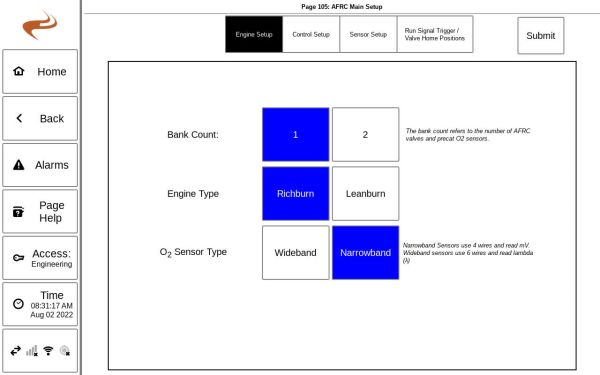
- Bank count: Select 1 or 2 banks for the number of valves used
- Engine type: Select the type of engine, richburn or leanburn
- O2 sensor type: Select narrowband for 4-wire sensors that read mV, and wideband for 6-wire sensors that read lambda ratio. Note that leanburn engines must use wideband.
Control Setup
Control type
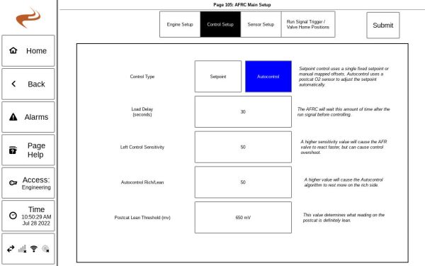
The AFRC Advanced has the ability to switch between control types “Setpoint” and “Auto Control”.
Auto Control
“Auto Control” is a patented control algorithm that uses both a pre-catalyst and post-catalyst O2 sensor to find the most appropriate target setpoint and maintains that setpoint through a variety of conditions. The target setpoint is not user adjustable and is managed by the AFRC Advanced without the need for any user input. “Auto Control” is only available for single bank and dual bank rich burn engine configurations. Multi-setpoint mapping is disabled while in this mode.
If “Auto Control” is selected as the control type, options will be made available to adjust the software to target either for a richer or leaner setting using the “Lean” and “Rich” buttons on the Engineering Setup screen (Pg. 207). By default, this setting is configured for equal CO and NOx reduction with a rich/lean setting value of 50. Due to varying site conditions, including fuel gas and ignition timing, this value may require an initial adjustment after installation. If lower CO emissions are desired at the expense of higher NOx, the rich/lean setting can be reduced by selecting the “Lean” button to adjust rich/lean value less than 50. Similarly, if lower NOx emissions are desired at the expense of higher CO, the rich/lean setting can be increased by selecting the “Rich” button to adjust rich/lean value greater than 50. The rich/lean value’s range is 0 to 100, where 0 is the maximum lean value and 100 is the maximum rich value.
When “Auto Control” is selected, an alarm is automatically generated on the Alarm Setup screen (Pg. 206) to switch to “Setpoint” control if the “Auto Control” setpoint drifts below 600 or above 800. If the alarm is triggered, it must be reset on the Alarms screen (Pg. 40) before “Auto Control” can be re-enabled. Typical cause of the drift outside of this range is an expired or ineffective Post-Cat O2 sensor.
Setpoint Control
“Setpoint” control mode controls off of a user, or mapping table, defined setpoint that corresponds with the desired emissions reduction. If desired, multiple setpoints can be used to automatically change the target setpoint based on sensor readings through the AFRC’s mapping feature.
Load Delay
The load delay setting adjusts the amount of time to delay the AFRC from taking control of the valve after it has detected a valid run signal and the sensors are warm. The intention of this configuration is to allow the engine to fully warm up and load before taking control.
The default value is set to 30 seconds, but the delay can optionally be configured to 1 minute, 5 minutes, 10 minutes, or 20 minutes.
Bank Sensitivity
The AFRC operates on a PID control loop to automatically adjust the valve to match the actual sensor reading to the target setpoint. By default, the control loop has been pre-tuned to find the target setpoint quickly while maintaining stability. If the condition exists where the valve needs to be either more or less responsive, the PID control loop can be adjusted by selecting the “Faster” or “Slower” buttons around the “Response Time” label. Slowing the valve response will decrease the sensitivity of the control loop, and increasing the valve response will increase the sensitivity of the control loop. The individual PID values are automatically adjusted based on the single “Response Time” value. The default “Response Time” value is 50 and is adjustable between 0 and 100.
Autocontrol Rich/Lean
If using Autocontrol mode, this setting helps determine how the control settles based on catalyst response. The default is 50, and higher values will make the controller settle more rich.
Sensor Setup
The AFRC Advanced has the following optional sensor inputs available for process monitoring, run signal, and mapping:
- Manifold Pressure Sensors (two available)
- Manifold Press Left" and "Manifold Press Right"
- Single bank configurations utilize the "Manifold Pressure Left" input
- Sensors are pre-configured for the system and can only be enabled or disabled
- Analog (one available)
- "ANALOG"
- Configurable to 0-5V, 1-5V, or 4-20mA
- Oil Pressure Switch (one available)
- "Oil Press Switch"
- Pre-configured as normally open (N/O) and can only be enabled or disabled
- Thermistor (one available)
- "Ambient"
- Thermocouple (one available)
- "Manifold"
- Type-K thermocouple only
- Magnetic Pickup (one available)
- "RPM"
- 1-100 Volts
These sensors are set up under the Main Setup of the AFRC.
Configuring the Analog Input
For the general purpose “ANALOG” input, go to the Sensor Setup slide of the AFRC main setup. The following fields are required:
- Name – Label of the sensor that will be displayed within the AFRC’s user interface
- Units – Units of the sensor
- Type – 4-20mA, 0-5 Volt, or 1-5V sensor output type
- Low Scale – Lowest output value of the sensor
- Full Scale – Highest output value of the sensor
Configuring RPM
The RPM input is configured by providing the pulses per revolution.
Run Signal and Valve Home
Run Signal Trigger
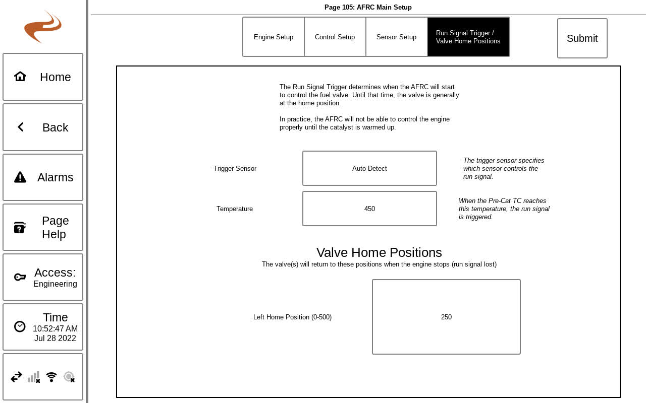
By default, the run signal selection is set to “Auto-Detect”, which scans enabled sensors for each module. The AFRC Advanced has three applicable inputs:
- Pre-catalyst thermocouple (terminals 24 and 25)
- Oil pressure switch (terminals 39 and 40)
- RPM (terminals 17 and 18)
If an AFRC Lite is installed, the only available run signal trigger sensor available is the pre-catalyst thermocouple (terminals 21 and 22).
Finally, the Ignition state can be used to determine run signal, if the ignition is in a running state the signal is set to Run.
Valve Home Position
This position gives the default starting value of the valve when the engine goes to stopped or the board powers up.
Alarm Setup
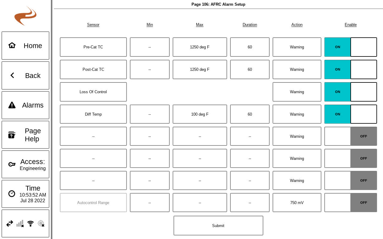
Up to eight (8) custom alarms can be configured on the AFRC to display within the Alarms screen (Pg. 40) or to trigger an external alarm though the error relay (terminal 6).
Configuring alarms is done on the Alarm Setup screen under Settings -> AFRC through the following parameters:
- Sensor – Input or condition to be monitored
- Only enabled sensors are available for selection
- Min – Minimum trigger value (optional)
- Max – Maximum trigger value (optional)
- Duration – Time, in seconds, for the sensor reading to either be below the minimum trigger value or above the maximum trigger value to become active
- Action – Action to take when alarm becomes active
- Warning – Displays the alarm within the Alarms screen (Pg. 40) and flashes the “Alarms” button on the footer of the display
- Shutdown – Closes the error relay (terminal 6), displays the alarm within the Alarms screen (Pg. 40), and flashes the “Alarms” button on the footer of the display
It is optional to select both “Min” and “Max” values, but at least one must be selected for sensor monitoring alarms. Selecting both values is available for monitoring a condition within a window, if desired.
Upon selecting the necessary information, the alarm is enabled by toggling the “Enable” toggle box next to the sensor’s name.
Note: Modifying an existing alarm requires the “Enable” toggle box to be toggled off and back on to take effect.
Note: A sensor can be placed in two alarm rows. For example, a PostCat TC alarm could be configured to shutdown at 1250, and generate a warning at 1000.
Autocontrol range alarm
If AutoControl is used on the AFRC Advanced, the final alarm in the Alarms Setup screen (Pg. 206) is the “AutoControl Range” alarm. This alarm can be used to fall back from “AutoControl” to “Setpoint” mode in the event the Post Catalyst O2 sensor milliVolt reading is pushed outside the set range, which can indicate the sensor is failing.
On a trigger of the alarm condition, the AFRC will go into “Setpoint” mode with a target setpoint valve defined by the alarm. The default is “777”. To change the fallback setpoint value, select the “Setpoint: 777” button within the alarm row.
This event will trigger an alarm, AFR062 (min trigger) or AFR063 (max trigger), on the Alarms screen (Pg. 40). This alarm must be reset in order to switch back from “Setpoint” mode to “AutoControl” mode. A security access level of Setup or Engineering is required to reset the alarm.


