Troubleshooting: Difference between revisions
No edit summary |
|||
| Line 1: | Line 1: | ||
== Governor / Speed Controller 20310 == | |||
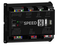
[[File:Gov_rendering.jpg|borderless|200px]] | |||
=== GOV Input Issues === | |||
==== RPM Reads “0” when cranking ==== | |||
General input wiring is shown below. | |||
[[File:GovmpuBasic.png|800px]] Wiring to module | |||
[[File:GovMpuPanel.png|800px]] Wiring through panel terminal block | |||
While the flywheel turns, the MPU generates an AC voltage wave where the frequency is equal to the speed of the flywheel movement. | |||
'''If no ICM is present on the system, OR if an ICM is present but two flywheel teeth MPUs are used:''' | |||
*Unplug the MPU and use a multimeter to measure AC Volts across the two MPU wires while cranking. It should show around 2-10V AC. If less is shown, then one of the following may be the cause: | |||
**The MPU is bad | |||
**The connection to the plug is bad | |||
**The engine is cranking too slowly to generate proper voltage | |||
**A stronger MPU is needed | |||
**The MPU is not close enough to the flywheel (typically should be ¼ to ½ turn out) | |||
*If test above passes, plug the MPU back in and check the AC voltage at the governor phoenix plug (pins 16/17) with the phoenix plug removed. Again it should be roughly 2-10V AC during cranking. If less is shown, there is a wiring problem in the harness or panel preventing the signal from reaching the governor. | |||
*If test above passes, plug the phoenix plug back into the governor and measure the AC voltage again while cranking. If it is low in this case, the governor MPU input may be damaged. | |||
*If above passes, check these final items: | |||
**Verify the flywheel teeth setting is correct | |||
**Verify there is no alarm for ‘governor sw error’ indicating the test version is installed | |||
**The governor board may be bad | |||
'''If an ICM is present on the system''' | |||
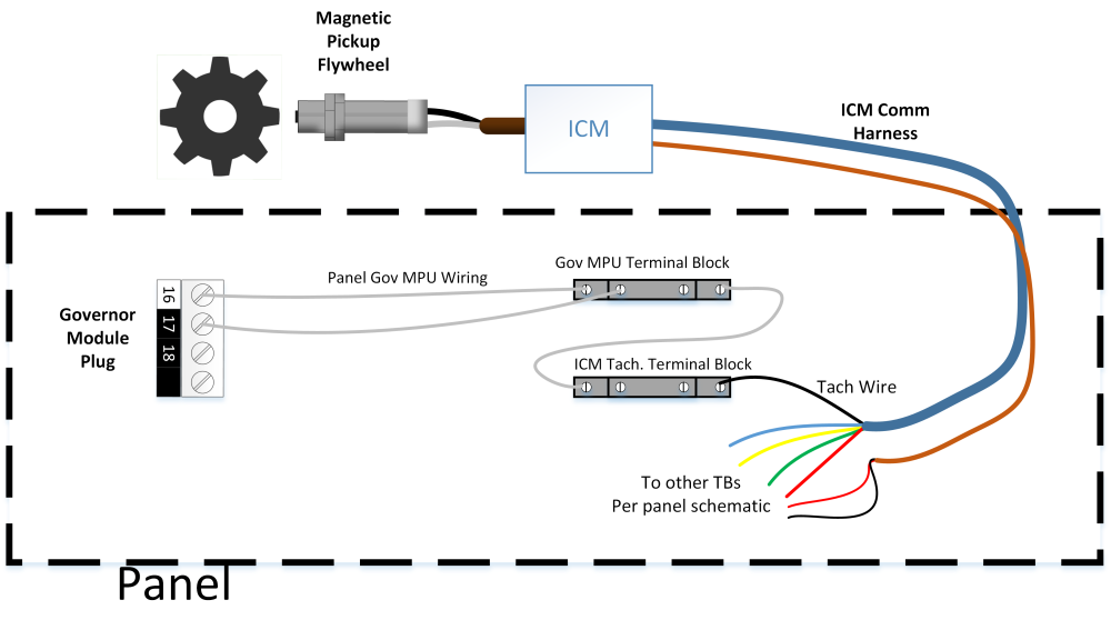
Often, the ICM Tachometer output is wired into the governor MPU input as shown. Note that the Tach goes to one of the governor MPU inputs, and the other is not connected (floating). | |||
[[File:GovMpuICM.png|1000px]] | |||
*Navigate to Ignition ‘Setup and Testing’->’Timing Calibration / Tachometer Output’, and verify that the tachometer pulses per revolution is set to the number of flywheel teeth. Verify also that both the ICM and governor main setups have the flywheel teeth setting correct. | |||
*If above is correct, check where the tach wire lands in the panel (which is the black wire on the ICM comm harness), and check the DC Hz on the tach wire (removed from terminal block) to ground. During crank, it should go from 0Hz to around 500Hz – 2KHz. If it does not: | |||
**Verify that the tach connection in the ICM box is secure | |||
**The ICM box may have a damaged tach circuit | |||
*If above passes, re-connect the tach wire and check the same DC Hz on the MPU+ pin on the governor (16) during crank then the MPU- pin (17) during crank. One of the two should have the 500Hz – 2KHz during crank. If not: | |||
**A connection may be miswired or missing from where the tach lands back to the governor module. A continuity check from the tach terminal block back to pins 16/17 of the governor can help track down a missing connection. | |||
**The governor board MPU input may be damaged | |||
==== MPU reads more than 0, but is not correct ==== | |||
If the MPU is reading a faulty RPM, verify the following | |||
*Make sure the flywheel teeth setting is correct | |||
*If an ICM is present on the system, verify that at the page Ignition ‘Setup and Testing’->’Timing Calibration / Tachometer Output’, the tachometer output pulses per revolution is set to the number of flywheel teeth | |||
*Verify that all connections are secure at the MPU plug and where wires land in the panel and governor module | |||
*The MPU may not be screwed in far enough. Verify it is within ½ to ¼ turn of the flywheel. | |||
*The MPU harness may be picking up noise. Make sure it is routed away from noise sources, and the drain wire is connected to ground. | |||
==== The throttle position does not show around 0% position when the engine is off ==== | |||
*The throttle may need to be re-calibrated. Navigate to Governor ‘Setup’ -> ‘Throttle Calibration’ and hit ‘calibrate now’. | |||
*If above does not fix the issue, see if the position appears to change at all while the calibration is taking place, if not, go to ‘Throttle not moving’ below | |||
**If the position is moving but the calibration still does not complete successfully, go to ‘throttle feedback problems’ below | |||
==== Throttle Feedback Problems ==== | |||
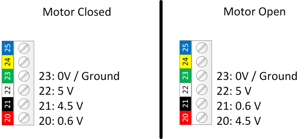
The Bosch throttle bodies use four feedback lines (terminals 20-23 on the governor module). Typical voltages are shown below. The actual feedback voltages (20/21) will vary ~0.3V between motors. The motor can be moved through calibration or manually. | |||
[[File:GovV.png|600px]] | |||
*If voltage does not appear on 22 (5V) but the governor module is powered up, there is likely a problem with the governor board | |||
*If voltage does appear on 22, but does not appear on 21/20, check for a bad connection somewhere between the module and the throttle body | |||
*If voltage appears on only one of 21/20, the other connection has a break between the module and the throttle body | |||
*If the voltages are roughly correct and the motor can move, but the calibration is still failing, it could be because of a problem with the pcb (preventing the reading of the voltage) or a bad throttle body (where the feedback potentiometer is not functioning correctly). | |||
==== Panel switches reading incorrectly ==== | |||
''' If the EMIT Brain is not Used ''' | |||
Each of the panel switch inputs (pins 8-14 on the governor module) operate by closing to ground. At any given time one of the inputs Idle/Auto/Manual should be closed to ground, and sometimes one of the Speed+/- may be as well. | |||
If no mode is closed to ground, the governor defaults to ‘idle’, so the idle pin (8) is not connected in panel applications. | |||
*If the module is not reacting properly to the switches, check continuity to ground on each of the input pins as the switch is moved in/out of the position related to that pin label. The pin should be connected to ground (showing <2 ohm) when the switch for that pin is selected | |||
**If this test fails, look for wiring errors or breaks in the switch blocks. Green blocks are normally open and red blocks are normally closed. | |||
**If this test seems to pass but the governor still shows the wrong switch position, the module may be bad. Try unplugging the two phoenix blocks for the switches and jumping pin 11 (ground) to one of the mode selects to see if they change the mode. | |||
== EIM 20200 == | == EIM 20200 == | ||
Revision as of 17:20, 21 July 2023
Governor / Speed Controller 20310
GOV Input Issues
RPM Reads “0” when cranking
General input wiring is shown below.
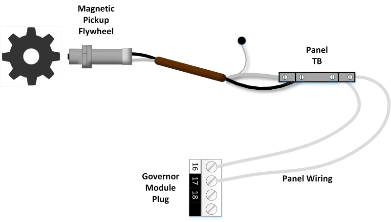 Wiring through panel terminal block
While the flywheel turns, the MPU generates an AC voltage wave where the frequency is equal to the speed of the flywheel movement.
If no ICM is present on the system, OR if an ICM is present but two flywheel teeth MPUs are used:
- Unplug the MPU and use a multimeter to measure AC Volts across the two MPU wires while cranking. It should show around 2-10V AC. If less is shown, then one of the following may be the cause:
- The MPU is bad
- The connection to the plug is bad
- The engine is cranking too slowly to generate proper voltage
- A stronger MPU is needed
- The MPU is not close enough to the flywheel (typically should be ¼ to ½ turn out)
- If test above passes, plug the MPU back in and check the AC voltage at the governor phoenix plug (pins 16/17) with the phoenix plug removed. Again it should be roughly 2-10V AC during cranking. If less is shown, there is a wiring problem in the harness or panel preventing the signal from reaching the governor.
- If test above passes, plug the phoenix plug back into the governor and measure the AC voltage again while cranking. If it is low in this case, the governor MPU input may be damaged.
- If above passes, check these final items:
- Verify the flywheel teeth setting is correct
- Verify there is no alarm for ‘governor sw error’ indicating the test version is installed
- The governor board may be bad
If an ICM is present on the system
Often, the ICM Tachometer output is wired into the governor MPU input as shown. Note that the Tach goes to one of the governor MPU inputs, and the other is not connected (floating).
- Navigate to Ignition ‘Setup and Testing’->’Timing Calibration / Tachometer Output’, and verify that the tachometer pulses per revolution is set to the number of flywheel teeth. Verify also that both the ICM and governor main setups have the flywheel teeth setting correct.
- If above is correct, check where the tach wire lands in the panel (which is the black wire on the ICM comm harness), and check the DC Hz on the tach wire (removed from terminal block) to ground. During crank, it should go from 0Hz to around 500Hz – 2KHz. If it does not:
- Verify that the tach connection in the ICM box is secure
- The ICM box may have a damaged tach circuit
- If above passes, re-connect the tach wire and check the same DC Hz on the MPU+ pin on the governor (16) during crank then the MPU- pin (17) during crank. One of the two should have the 500Hz – 2KHz during crank. If not:
- A connection may be miswired or missing from where the tach lands back to the governor module. A continuity check from the tach terminal block back to pins 16/17 of the governor can help track down a missing connection.
- The governor board MPU input may be damaged
MPU reads more than 0, but is not correct
If the MPU is reading a faulty RPM, verify the following
- Make sure the flywheel teeth setting is correct
- If an ICM is present on the system, verify that at the page Ignition ‘Setup and Testing’->’Timing Calibration / Tachometer Output’, the tachometer output pulses per revolution is set to the number of flywheel teeth
- Verify that all connections are secure at the MPU plug and where wires land in the panel and governor module
- The MPU may not be screwed in far enough. Verify it is within ½ to ¼ turn of the flywheel.
- The MPU harness may be picking up noise. Make sure it is routed away from noise sources, and the drain wire is connected to ground.
The throttle position does not show around 0% position when the engine is off
- The throttle may need to be re-calibrated. Navigate to Governor ‘Setup’ -> ‘Throttle Calibration’ and hit ‘calibrate now’.
- If above does not fix the issue, see if the position appears to change at all while the calibration is taking place, if not, go to ‘Throttle not moving’ below
- If the position is moving but the calibration still does not complete successfully, go to ‘throttle feedback problems’ below
Throttle Feedback Problems
The Bosch throttle bodies use four feedback lines (terminals 20-23 on the governor module). Typical voltages are shown below. The actual feedback voltages (20/21) will vary ~0.3V between motors. The motor can be moved through calibration or manually.
- If voltage does not appear on 22 (5V) but the governor module is powered up, there is likely a problem with the governor board
- If voltage does appear on 22, but does not appear on 21/20, check for a bad connection somewhere between the module and the throttle body
- If voltage appears on only one of 21/20, the other connection has a break between the module and the throttle body
- If the voltages are roughly correct and the motor can move, but the calibration is still failing, it could be because of a problem with the pcb (preventing the reading of the voltage) or a bad throttle body (where the feedback potentiometer is not functioning correctly).
Panel switches reading incorrectly
If the EMIT Brain is not Used
Each of the panel switch inputs (pins 8-14 on the governor module) operate by closing to ground. At any given time one of the inputs Idle/Auto/Manual should be closed to ground, and sometimes one of the Speed+/- may be as well.
If no mode is closed to ground, the governor defaults to ‘idle’, so the idle pin (8) is not connected in panel applications.
- If the module is not reacting properly to the switches, check continuity to ground on each of the input pins as the switch is moved in/out of the position related to that pin label. The pin should be connected to ground (showing <2 ohm) when the switch for that pin is selected
- If this test fails, look for wiring errors or breaks in the switch blocks. Green blocks are normally open and red blocks are normally closed.
- If this test seems to pass but the governor still shows the wrong switch position, the module may be bad. Try unplugging the two phoenix blocks for the switches and jumping pin 11 (ground) to one of the mode selects to see if they change the mode.
EIM 20200
Screen boots to the EMIT logo, but is stuck there
- Usually this is an issue with the internal memory and must be repaired by EMIT
- The SLC-SD card lock may be grounded against the case
- The SLC-SD card itself may have an issue
Screen boots past the EMIT logo, but the application does not start
- Usually this will require repair
- An SLC-SD card from a different EIM was used and the encryption does not match (Cards cannot be swapped between EIMS)
- The SLC-SD card may be bad
Screen is always black
- Try cycling power on the screen
- Verify that the input voltage is between 12 and 30 VDC
- If input power is good but the green power LED does not come on, the EIM needs repair
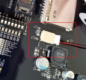
- Behind back cover, verify that the backlight connection is in all the way
- If all of the above is ok and there is still no boot, the EIM needs repair. It is most likely an issue with the SLC-SD card.
Touch screen input does not detect press in correct location
- The touchscreen may need to be re-calibrated under “System Settings” -> “About” -> “Calibrate Touch Screen”
- If debris accumulates under the bezel it can screw up touch detection. Cleaning around the bezel can fix this issue.
- Sometimes the screen bracket is too tight causing this issue. Remove the back cover and loosen the left and right screen screws slightly (3 per side that go into bezel)
