ECU Run Signal Debugging: Difference between revisions
Sean Sanders (talk | contribs) No edit summary |
Sean Sanders (talk | contribs) No edit summary |
||
| (One intermediate revision by the same user not shown) | |||
| Line 7: | Line 7: | ||
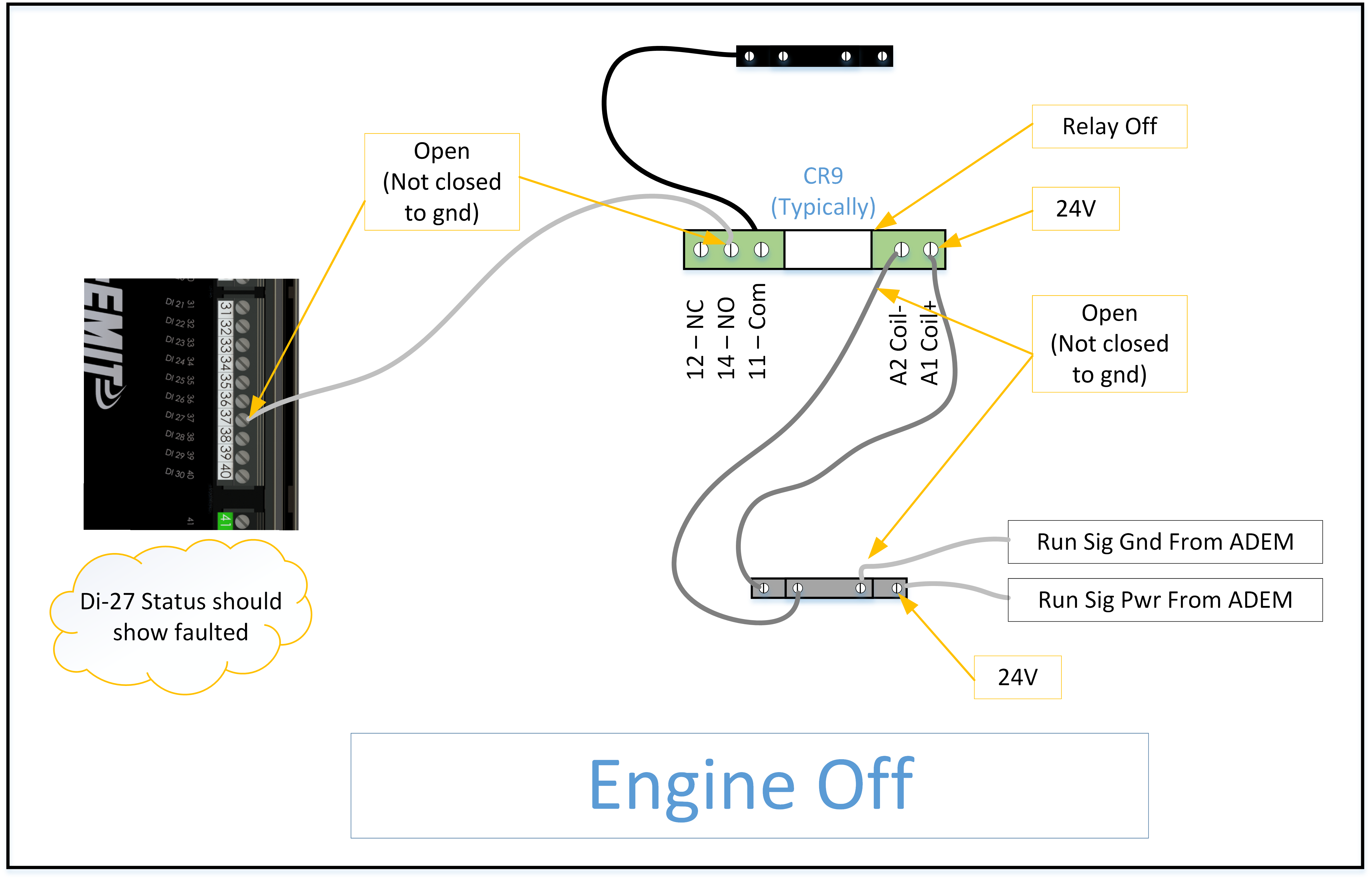
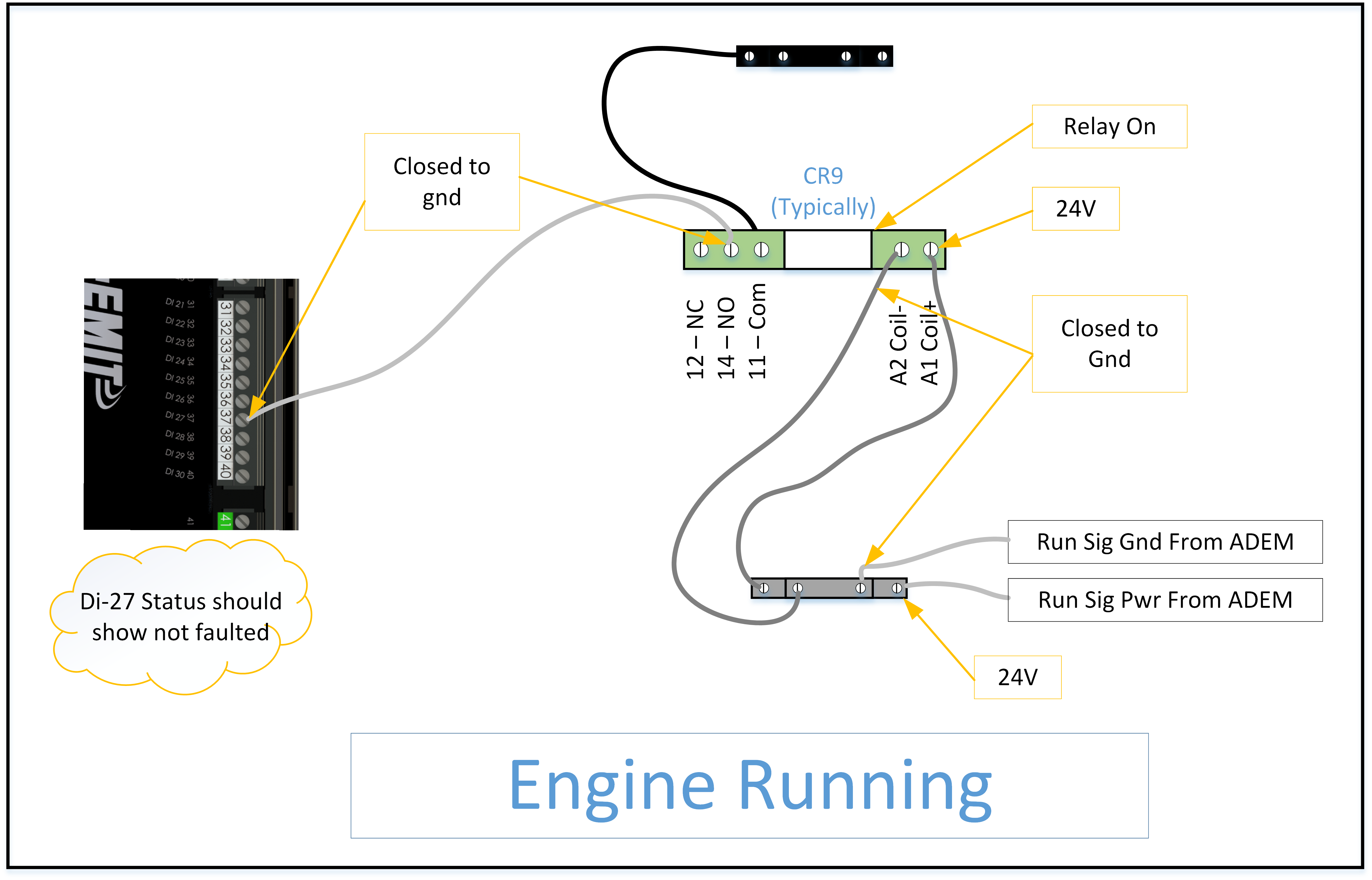
The following show typical wiring and expected signals when the unit is off or on. | The following show typical wiring and expected signals when the unit is off or on. | ||
[[File:Eng off2.png]] | |||
[[File:Eng running2.png]] | |||
[[File:Eng running2.png | |||
Latest revision as of 17:55, 27 July 2022
CAT->Brain (Annunciator) Interface
The CAT panel has one return signal to tell the annunciator that the engine is running. On Panel schematics, this is called “ADEM RUN SIGNAL”, and closes a relay to ground. The contact of the relay is wired to digital input 27, which is automatically filled in as a normal digital input called “ADEM RUN STATUS”.
The coil side of the relay is wired to two terminal blocks. On most ADEM systems, the run signal is ground during run, so the other coil side of the relay is wired to keyswitch power. On some ADEM systems, the run signal is power during run, so the other side of the coil is wired to ground. Both cases result in a relay that is powered during run. The relay should go from off to on when the unit starts, and the input on the annunciator (DI-27) will go from faulted to unfaulted when the relay comes on.
Verify when the engine is off that DI-27 shows FAULTED in the fault list (home screen 'state' box selection, then 'faults' tab).
The following show typical wiring and expected signals when the unit is off or on.

