Panel to ADEM(r) Interfacing: Difference between revisions
| (4 intermediate revisions by the same user not shown) | |||
| Line 4: | Line 4: | ||
The interfacing and operation between older “ADEM 3” and newer “ADEM 4” ECUs are similar, but vary in some ways. This document describes how the Brain and/or panel is wired to the ADEM in different cases, and how the control operates. | The interfacing and operation between older “ADEM 3” and newer “ADEM 4” ECUs are similar, but vary in some ways. This document describes how the Brain and/or panel is wired to the ADEM in different cases, and how the control operates. | ||
This page gives background information about the different signals. For troubleshooting steps, see [[Troubleshooting#Control_Issues]] and [[Troubleshooting#Output_Issues]]. | |||
==Start / Stop / Fault Control== | ==Start / Stop / Fault Control== | ||
| Line 61: | Line 63: | ||
Note 2: CG-137 has two e-stop loops in parallel that both have to be broken at the same time. For this engine the E-stop needs three contact blocks to add our E-stop to the CAT loop-- two for the CAT loop and one for the Brain shutdown. | Note 2: CG-137 has two e-stop loops in parallel that both have to be broken at the same time. For this engine the E-stop needs three contact blocks to add our E-stop to the CAT loop-- two for the CAT loop and one for the Brain shutdown. | ||
===CAT Setup Notes=== | |||
Some engines have special setup through CAT ET to make sure the start/stop inputs work as intended. If an engine is not listed below it has no special setup for start / stop. | |||
'''CG137/3500/3600 A4 OCP''' | |||
*Digital Input 3 Usage Type: Command / Status Parameter | |||
*Digital Input 3 Active State Configuration: Low | |||
*Digital Input 3 Command / Status Parameter Data Identification: Engine Control Switch in Stop | |||
*Digital Input 4 Usage Type: Command / Status Parameter | |||
*Digital Input 4 Active State Configuration: Low | |||
*Digital Input 4 Command / Status Parameter Data Identification: Engine Control Switch in Run | |||
*Engine State Control Input Configuration: CAN Input | |||
*Engine State Control Secondary Input Configuration: Not Installed | |||
'''CG137/3600 A4 HMI''' | |||
*Engine State Control - Driven Equipment Delay Time: 0.0 sec | |||
==Speed Control== | ==Speed Control== | ||
| Line 86: | Line 108: | ||
Except on a few very old panels, the panels will have an IDLE/MANUAL/AUTO selector switch and a manual +/- switch. When in IDLE, the Brain will output the minimum speed, and the IDLE relay will be on. When in MANUAL, the Brain will change the output speed as the SPEED+ or SPEED- switches are held. When in AUTO, the Brain will output the configured auto speed- either a fixed speed, or based off of a sensor condition (e.g. suction pressure). If another manual speed knob exists on the ADEM in this case, it should be unwired and removed to avoid confusion from having two manual speed knobs. | Except on a few very old panels, the panels will have an IDLE/MANUAL/AUTO selector switch and a manual +/- switch. When in IDLE, the Brain will output the minimum speed, and the IDLE relay will be on. When in MANUAL, the Brain will change the output speed as the SPEED+ or SPEED- switches are held. When in AUTO, the Brain will output the configured auto speed- either a fixed speed, or based off of a sensor condition (e.g. suction pressure). If another manual speed knob exists on the ADEM in this case, it should be unwired and removed to avoid confusion from having two manual speed knobs. | ||
==Start Sequence== | |||
*On power up, unit is STOPPED | |||
**DRIVEN EQUIPMENT READY output is set to faulted / not ready | |||
**START/RUN output is off (stopped) | |||
*Operator presses RESET | |||
**Unit will go to STANDBY | |||
**ADEM receives DRIVEN EQUIPMENT READY signal (but not START/RUN signal) so that any faults can be cleared if needed | |||
*Operator presses START | |||
**Assuming all A and ESD faults are clear, unit goes to next state | |||
*Blowdown, purge, prelube sequences will run if needed | |||
*ADEM Start Sequence | |||
**Panel supplies ‘ADEM RUN/START’ signal | |||
**Start gas block valve opens, if it did not already come on during STANDBY | |||
**ADEM cranks and starts engine | |||
**If ADEM fails to start engine (crank terminate RPM not met) before the max ADEM startup time is met, sequence will fault with “ECU Failed to Start Engine”. | |||
**Once crank terminate RPM is met, state moves to RUNNING (Which may have an idle hold and/or load delay timer active) | |||
**B1 and B2 timer begin counting down | |||
*Warmup | |||
**The ECU will turn on the ADEM RUN SIGNAL relay which will clear DI-27 ADEM RUN STATUS of the Brain | |||
**The panel will hold the ‘ADEM IDLE/RATED’ input at idle until the idle hold condition is met (regardless of panel SPEED MODE switch position). | |||
**EIM will display “RUN” and “Idle permissive not met” | |||
**B1 and B2 timers will count down and expire normally. Operator RESET presses will reset these timers | |||
*Running | |||
**Once the ‘Idle Hold Condition’ is met, the ‘ADEM IDLE/RATED’ input will be switched to RATED | |||
**The speed output to the ADEM will now changed based on the operator SPEED MODE switch position | |||
==EDT (Data) Connection== | ==EDT (Data) Connection== | ||
Latest revision as of 18:00, 15 February 2024
Overview
On various Caterpillar engines, the ADEM(r) system is used to control the engine operation, and the EMIT Brain (Annunciator) is used to monitor and protect the compressor (which falls under the CAT category “Driven Equipment”). In some cases, the ADEM is generically called an ECU (Engine Control Unit). Similar to other ECUs (E.g. older CAT EIS, or Waukesha ESM) the ADEM features a number of connections that are used by the panel to control engine operation- primarily start/stop and speed control.
The interfacing and operation between older “ADEM 3” and newer “ADEM 4” ECUs are similar, but vary in some ways. This document describes how the Brain and/or panel is wired to the ADEM in different cases, and how the control operates.
This page gives background information about the different signals. For troubleshooting steps, see Troubleshooting#Control_Issues and Troubleshooting#Output_Issues.
Start / Stop / Fault Control
The ADEM has signals connected for controlling start/stop of the engine, and return signal(s) for signifying an engine shutdown. These signals vary on different engines, but the only difference from a panel perspective is how the signals are wired. In general, CAT will publish a document describing customer interfacing to the ECU, and the wiring can be adapted to fit the engine requirements.
Brain 🡆 CAT Interface
The Brain is configured to be in a general ADEM-interfacing mode by going to “Outputs Setup” -> “ECU Selection”, and selecting “CAT ADEM”. This tells the system that the logic should be used to drive an ADEM.
There are two signals from the EMIT panel to the CAT panel for run control: the Run/Stop signal and the driven equipment ready signal.
Run/Stop Signal
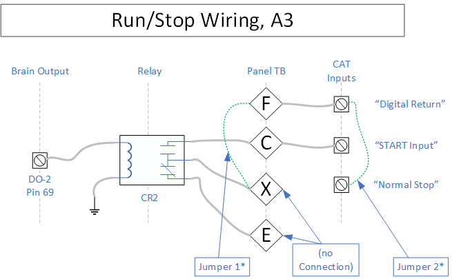
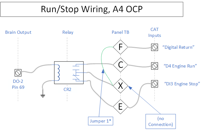
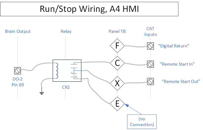
The Run/Stop signal is controlled by digital out 2 (pin 69) of the Brain, which on the great majority of panels drives relay #CR2. This relay should be ON to run and OFF to stop. On ADEM 3 systems, this can close a normally open contact from DIGITAL RETURN to RUN/START to run the engine. On ADEM 4 systems, there is sometimes an additional STOP input that is wired to the NC side of this relay, and is grounded during stop. On HMI A4 systems, this relay closes a dry contact to run the engine. The scenarios are shown below.
Jumper 1: On a 14280-2001 panel this is from 113B to 112B to supply "Digital Return" to "X". On other panels this jumper is not present, instead normal internal panel wiring supplies "Digital Return" to the common contact of CR2 at all times.
Jumper 2: This is inside the CAT panel from Normal Stop to return
Jumper 1: On a 14280-2001 panel this is from 113B to 112B to supply "Digital Return" to "X". On other panels this jumper is not present, instead normal internal panel wiring supplies "Digital Return" to the common contact of CR2 at all times.
Note: On HMI engines, the Digital return signal is still used for some other circuits but is not used for the run/stop circuit.
Driven Equipment Ready Signal
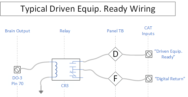
This signal tells the CAT panel that the unit is safe to run, and is almost always controlled by Brain digital out 3 (pin 70). The digital output can be configured as the A4 Driven Equipment Ready pin by going to “Settings” -> “Brain” -> “Output Setup” -> “Output to Function Assignment” and then selecting an unused digital output and changing the function to “ADEM 4 DRIVEN EQUIP READY”. This pin will be on when D.E.R. should be in RUN and off (floating) when D.E.R. should be stopped/faulted. Almost always this wires to a relay #CR3 which closes digital return (ground) to the ADEM driven equipment ready. The D.E.R. pin comes on during STANDBY mode and through startup. This allows the CAT panel alarm to be cleared in panel standby state. Normal startup procedure is to hit RESET on the panel, clear the CAT alarm, then press START on the panel.
From the CAT factory, the DIGITAL EQUIPMENT READY is wired to always run with a jumper, which should be removed during panel installation. Some older ADEM 3 systems also have a NORMAL STOP input which should be permanently wired to DIGITAL RETURN.
Note: On some older panels, driven equipment ready was driven from Pin 10 of the Brain. This pin goes to ground when the Brain reaches the full RUN state (and the fuel valve should come on).
CAT 🡆 Brain interface
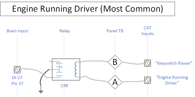
The CAT panel has one return signal to tell the Brain that the engine is running. On Panel schematics, this is called “ADEM RUN SIGNAL”, and closes a relay to ground. The contact of the relay is wired to digital input 27 of the Brain which is a normal digital input called “ADEM RUN STATUS”.
The coil side of the relay is wired to two terminal blocks. On most ADEM systems, the run signal is grounded during run, so the other coil side of the relay is wired to keyswitch power. On some ADEM systems the run signal is powered during run, so the other side of the coil is wired to ground. Both cases result in a relay that is powered during run. The relay should go from off to on when the unit starts, and the input on the Brain (DI-27) will go from faulted to unfaulted when the relay comes on.
E-Stop
The E-Stop on the EMIT panel has two contacts, one of which is wired to a digital input on the Brain, and the other is wired to the ADEM. This way when the E-Stop is pressed both systems should get the signal.
The panel schematic wiring table shows how the E-Stop ADEM contact is wired on different engines. In general, the connection to the E-Stop on the CAT panel is broken to additionally flow through the EMIT Panel E-Stop. Most ADEM panels have a jumper installed for this purpose that can be removed to add the EMIT E-Stop.
Note: Some ADEM systems have two separate E-Stop loops running through the emergency stop switches’ contacts. One is maintained to ground for a digital E-Stop signal, and the other is maintained to power to supply fuel valve power. In this scenario, it is only the digital ground loop that is broken and routed through the EMIT panel.
Note 2: CG-137 has two e-stop loops in parallel that both have to be broken at the same time. For this engine the E-stop needs three contact blocks to add our E-stop to the CAT loop-- two for the CAT loop and one for the Brain shutdown.
CAT Setup Notes
Some engines have special setup through CAT ET to make sure the start/stop inputs work as intended. If an engine is not listed below it has no special setup for start / stop.
CG137/3500/3600 A4 OCP
- Digital Input 3 Usage Type: Command / Status Parameter
- Digital Input 3 Active State Configuration: Low
- Digital Input 3 Command / Status Parameter Data Identification: Engine Control Switch in Stop
- Digital Input 4 Usage Type: Command / Status Parameter
- Digital Input 4 Active State Configuration: Low
- Digital Input 4 Command / Status Parameter Data Identification: Engine Control Switch in Run
- Engine State Control Input Configuration: CAN Input
- Engine State Control Secondary Input Configuration: Not Installed
CG137/3600 A4 HMI
- Engine State Control - Driven Equipment Delay Time: 0.0 sec
Speed Control
There are two speed control signals to the ADEM: “Idle” signal, and speed target. Each are discussed below.
Idle Signal
Typically, the ADEM has one input that is used to idle the engine when grounded. This is usually called “IDLE/RATED SPEED” on the CAT engine schematic, though for newer ADEMs an input has to be configured to have this function. Some engines will have this pin operate as ground to idle, and some will be ground to end idle instead. During idle the ADEM will make the engine hold idle speed, also called “Engine Lo Idle” in the CAT config.
In the panel there will be an idle relay that turns on during idle, and is typically driven from digital output #4. The relay will come on when the panel is in the "idle" switch position or during an Idle Hold. The common of the relay will ultimately connect to digital return, and depending on the engine another contact (normally open or normally closed) will wire back to the IDLE/RATED input of the ADEM. The wiring table in the back of the schematic shows which pin to use for a given engine.
Speed Target Signal
The Brain can output a target speed signal on one of the analog outs. This can be wired to the ADEM in various ways to control the speed of the engine.
During the Brain “Speed Output” setup, the user selects an output, what type of analog output it is, and what speeds it corresponds to. These settings should match what the engine is expecting.
Newer ADEM systems have both 4-20 mA (current) inputs and voltage input(s) that can be configured as the speed target input. Older systems tend to have only a voltage input for speed. The engines startup special instruction document generally gives the preferred option for speed control input.
- Current Input: When the Brain outputs 4mA, the engine runs at the configured “Min Hi Idle” speed. When the Brain outputs 20mA, the engine runs at the configured “Max Hi Idle” speed. In between, the input target is scaled linearly.
- Voltage input: Typically on older systems, the voltage input expects 0.5v – 4.5v for the min to max speed. From the factory this comes from a potentiometer, which is disconnected. On some engines it uses 0-5v range instead.
Panel Switches
Except on a few very old panels, the panels will have an IDLE/MANUAL/AUTO selector switch and a manual +/- switch. When in IDLE, the Brain will output the minimum speed, and the IDLE relay will be on. When in MANUAL, the Brain will change the output speed as the SPEED+ or SPEED- switches are held. When in AUTO, the Brain will output the configured auto speed- either a fixed speed, or based off of a sensor condition (e.g. suction pressure). If another manual speed knob exists on the ADEM in this case, it should be unwired and removed to avoid confusion from having two manual speed knobs.
Start Sequence
- On power up, unit is STOPPED
- DRIVEN EQUIPMENT READY output is set to faulted / not ready
- START/RUN output is off (stopped)
- Operator presses RESET
- Unit will go to STANDBY
- ADEM receives DRIVEN EQUIPMENT READY signal (but not START/RUN signal) so that any faults can be cleared if needed
- Operator presses START
- Assuming all A and ESD faults are clear, unit goes to next state
- Blowdown, purge, prelube sequences will run if needed
- ADEM Start Sequence
- Panel supplies ‘ADEM RUN/START’ signal
- Start gas block valve opens, if it did not already come on during STANDBY
- ADEM cranks and starts engine
- If ADEM fails to start engine (crank terminate RPM not met) before the max ADEM startup time is met, sequence will fault with “ECU Failed to Start Engine”.
- Once crank terminate RPM is met, state moves to RUNNING (Which may have an idle hold and/or load delay timer active)
- B1 and B2 timer begin counting down
- Warmup
- The ECU will turn on the ADEM RUN SIGNAL relay which will clear DI-27 ADEM RUN STATUS of the Brain
- The panel will hold the ‘ADEM IDLE/RATED’ input at idle until the idle hold condition is met (regardless of panel SPEED MODE switch position).
- EIM will display “RUN” and “Idle permissive not met”
- B1 and B2 timers will count down and expire normally. Operator RESET presses will reset these timers
- Running
- Once the ‘Idle Hold Condition’ is met, the ‘ADEM IDLE/RATED’ input will be switched to RATED
- The speed output to the ADEM will now changed based on the operator SPEED MODE switch position
EDT (Data) Connection
The engine data translator built into the DCT can pull data from the ADEM and bring it into the EMIT system. On old panels, an EDT module can be added for this purpose. This has two main benefits:
- The CAT data is available via panel Modbus from the screen along with the compressor data
- Datalogs will include the CAT data for both long-term logs and shutdown logs to be compared against compressor data
New ADEM systems have one primarily data link- the CAN data link. This is wired to the “ECU CAN” port. This can be wired by directly connecting to terminal blocks in the CAT panel. The CAT wire colors are as follows, and will always be grouped together:
- CAN L: Green
- CAN H: Yellow
- CAN Cmn: Dark Gray
Older ADEM 3 systems have both the CAN data link and the CDL (Cat Data Link), with a variety of data on each. The CAN data link can still be connected as described above, and an additional connection added for the CDL pins. These are connected as follows:
- CDL+ (Pink in the CAT panel): To EDT “CDL” “A”
- CDL- (Purple in the CAT panel): To EDT “CDL” “B”
Termination Resistor Note
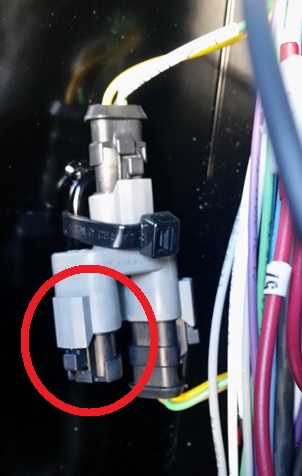
Generally the ADEM panel will have a CAN termination resistor plug that looks like this:
This plug should be removed after connecting the CAN bus to the EMIT panel, since the DCT becomes the new end of the network. This assumes the red switch by the ECU CAN port of the screen is terminated (switched up).
Engine Reference
Pins
| Pin Name | 3600A4 HMI/CG HMI | 3500 A3 | 3600 A3 | 3500/3600 A4 OCP | CG137 A4 OCP |
|---|---|---|---|---|---|
| A: Run Relay Ground | 20 | 29 | 14 | 1-20 | 4 |
| B: Run Relay Power | 48 | 18 | 4 | 1-52 | 13 |
| C: ADEM Start | 71 (full encl)
5 (base encl) |
16 | 6 | 2-93 | 59 |
| D: Driven Equip Ready | 51 | 17 | 21 | 1-51 | 16 |
| E: Stop | - | - | - | 2-82 | 76 |
| F: Digital Return | 5 | 15 | 8 | 1-61 | 15 |
| G: Return, jump to H | - | 40 | 2 | - | - |
| H: Normal stop, jump to G | - | 19 | 25 | - | - |
| J: Speed Input | 10 | 7 | 37 | 2-70 | 47 |
| K: Speed Common | 11 | 8 | 38 | 2-79 | 51 |
| L: Rated Speed (Ground = Rated) | - | 22 | 22 | - | - |
| M: Engine Failure | - | 25 | 9 | 2-84 | - |
| N: ESD 1A | 23 | - | - | - | - |
| O: ESD 1B | 23 | - | - | - | - |
| P: Idle (Ground = Idle) | 58 | - | - | 1-58 | 58 |
| Q: CDL+ | - | 13 | 31 | - | - |
| R: CDL- | - | 14 | 32 | - | - |
| S: CAN+ | 50 | 35 | 33 | 1-50 | 3 |
| T: CAN- | 34 | 36 | 34 | 1-34 | 2 |
| V: ESD2A | 22 | - | - | - | - |
| W: ESD2B | 22 | - | - | - | - |
| X: START/STOP IN | 72 (full encl)
47 (base encl) |
- | - | - | - |
Speed Control Setup Notes
3300 A4
- Uses voltage mode input on 7
- Uses idle pin on 8, ground to idle
Setup notes:
- Remove original speed pot wire at pin 7
3500 A3
- Uses voltage mode input on 7 OR 4-20mA input on 10
- Uses idle pin on 22, unground for idle
Setup notes:
- Desired speed input has to be set with ET as 0-5v or 4-20 mA, as "Desired Engine Speed Input Configuration"
- Remove original speed pot wire at pin 7 if using voltage mode
3600 A3
- Uses voltage mode input on 37 OR 4-20mA input on 40
- Uses idle pin on 22, unground for idle
Setup notes:
- Desired speed input has to be set with ET as 0-5v or 4-20 mA, as "Desired Engine Speed Input Configuration"
- Remove original speed pot wire at pin 7 if using voltage mode
35/3600 OCP
- Uses voltage mode input on pin 2-70
- There is also 4-20mA input on EIC pin 10 but this is not recommended for use
- Uses idle pin on 1-58, ground for idle
Setup notes:
- 2-70 and 2-70 are Analog Input 3
- "Desired Speed Input Configuration": CAN Input
- "Analog Input #3 Signal Type": Voltage
- "Analog Input #3 Supply Voltage": 5v
- "Analog Input #3 Signal Range": 0-5v
- "Analog Input #3 Data Identification": Desired Engine Speed Command
- "Analog Input #3 Minimum Data Range": 700 or other min speed
- "Analog Input #3 Maximum Data Range": 1000 or other max speed
CG137 A4 OCP
- Uses voltage or current input on pin 47
- Uses idle pin on 58, ground for idle
Setup Notes:
- 47 and 51 are Analog Input 3
- "Desired Speed Input Configuration": CAN Input
- "Analog Input #3 Signal Type": Current for 4-20mA or Voltage for 0-5V
- "Analog Input #3 Supply Voltage": Disabled
- "Analog Input #3 Signal Range": 4-20mA or 0-5V
- "Analog Input #3 Data Identification": Desired Engine Speed Command
- "Analog Input #3 Minimum Data Range": 1200 or other min speed
- "Analog Input #3 Maximum Data Range": 1800 or other max speed
3600/ CG137 HMI
- Uses 4-20mA input at 10
- There is also a voltage input at 15 but it is not recommended
- Uses idle pin at 58, ground for idle
Setup notes:
- "Desired Engine Speed Configuration": 4-20mA input or 0-5 VDC depending on pin
- "Secondary Desired Speed Input": Not installed
- "Low Idle Speed": 550 or as needed
- "Maximum Engine High Idle Speed": 1000 or other
- "Minimum Engine High Idles Speed": 700 or other
