Speed Setup: Difference between revisions
Sean Sanders (talk | contribs) (Created page with "Video available for this topic: https://www.youtube.com/watch?v=PAmjcq7CPt0 === ENGINE CONDITION === For proper AFRC operation, it is critical that the engine be in good operational status. Verify the following before running the AFRC: * Valves are adjusted to factory specification * Spark plugs are properly gapped and in good condition * Cylinders have good compression * Mixers are in good condition and regulator fuel pressure is set to factory specification * Fuel co...") |
No edit summary |
||
| (3 intermediate revisions by one other user not shown) | |||
| Line 1: | Line 1: | ||
After initial install, or when settings changes are needed, the Governor setup screens are used. The setup screens are accessed by selecting “Settings” on the Home screen, then the “Speed Controller” button. An access level of ''Setup'' or higher is needed to access these screens. | |||
=== ENGINE | === STEP 1: ENGINE SETTINGS === | ||
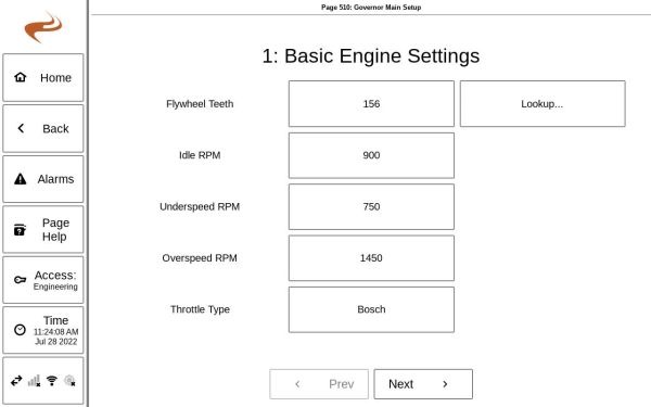
Step 1 of governor setup specifies the basic engine settings. These are the number of flywheel teeth, the idle speed for when the panel switch is in “Idle”, and the speed alarm values. After initial setup, these settings are not commonly changed. | |||
[[File:Governor Setup 1.jpg|600px]] | |||
''Setup Step 1'' | |||
If an underspeed alarm is not needed, it can be set to “0”. The speed alarm will always shut down the engine regardless of the control mode or condition. If an RPM setpoint higher than the overspeed alarm is specified, the setting will be allowed, but once the engine hits the overspeed value it will be shut down. | |||
=== STEP 2: CONTROL SELECTION === | |||
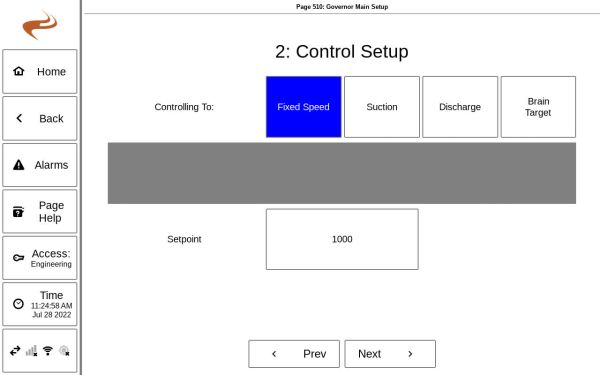
In step 2 of the governor setup, the setpoint type and value are specified. For the fixed speed control type, the setpoint is an engine RPM. For suction or discharge control, the setpoint is a PSI value. | |||
[[File:Governor Setup 2.jpg|600px]] | |||
If fixed speed control is selected, the setup will skip to Governor Setup Review after this step. | |||
For pressure control modes, the control type can be "Setpoint, Deadband" or "Linear Ramp". (Note: Linear Ramp mode requires software version 848 or newer). | |||
The | '''Setpoint, Deadband''': In this mode, a pressure setpoint and deadband is given. If the pressure is outside of the range [Setpoint +/- Deadband], the speed will change (with the direction depending on if it is suction or discharge control). Within the deadband, the speed will not change. The speed will increase or decrease only until the speed hits a range limit, given on the next setup page. | ||
'''Linear Ramp''': For linear ramp mode, a low and high pressure will be given. Between this high and low value, the speed target will be calculated linearly with respect to the low and high operating RPM. Example setup (suction control): | |||
* Low pressure: 20 PSI | |||
* High pressure: 30 PSI | |||
* Low RPM: 1200 | |||
* High RPM: 1600 | |||
In the above example, if the current suction input pressure is 25 PSI, the RPM target will be 1400 RPM. | |||
=== STEP 3: PRESSURE CONTROL SETTINGS === | |||
If using a pressure control mode (suction or discharge), step 3 will specify some additional settings. | |||
The High and Low Auto RPM specify the operating range of the engine while controlling to the specified pressure. The Governor will not let the engine out of this range, even if the pressure is still too low or high. This is separate from the over- and underspeed alarms mentioned earlier, which specify the absolute min and max speed for the engine. | |||
The change rate determines how fast the Governor will ramp up or down the RPM when in a pressure control mode. The default is 50 RPM/s. A lower value will result in less tight control, but more stable operation because the engine will ramp more slowly. | |||
Note: Generally, for suction control the response rate can be lower, since a well (or upstream supply) changes pressure so slowly. For discharge control, the response rate is usually higher. | |||
=== | === SETUP SUMMARY === | ||
The | The setup summary page shows a summary of all the selected settings for the Governor. If the page looks correct, the “Submit” button can be pressed to send the settings to the Governor. | ||
=== | === NOTE ON SENSOR SETUP (PRESSURE CONTROL ONLY) === | ||
If using pressure control mode and the system does NOT have an EMIT annunciator, then the pressure sensor needs to be set up to wire to the governor module. See [[Speed Sensor Setup]] | |||
If | |||
Latest revision as of 21:53, 29 July 2022
After initial install, or when settings changes are needed, the Governor setup screens are used. The setup screens are accessed by selecting “Settings” on the Home screen, then the “Speed Controller” button. An access level of Setup or higher is needed to access these screens.
STEP 1: ENGINE SETTINGS
Step 1 of governor setup specifies the basic engine settings. These are the number of flywheel teeth, the idle speed for when the panel switch is in “Idle”, and the speed alarm values. After initial setup, these settings are not commonly changed.
Setup Step 1
If an underspeed alarm is not needed, it can be set to “0”. The speed alarm will always shut down the engine regardless of the control mode or condition. If an RPM setpoint higher than the overspeed alarm is specified, the setting will be allowed, but once the engine hits the overspeed value it will be shut down.
STEP 2: CONTROL SELECTION
In step 2 of the governor setup, the setpoint type and value are specified. For the fixed speed control type, the setpoint is an engine RPM. For suction or discharge control, the setpoint is a PSI value.
If fixed speed control is selected, the setup will skip to Governor Setup Review after this step.
For pressure control modes, the control type can be "Setpoint, Deadband" or "Linear Ramp". (Note: Linear Ramp mode requires software version 848 or newer).
Setpoint, Deadband: In this mode, a pressure setpoint and deadband is given. If the pressure is outside of the range [Setpoint +/- Deadband], the speed will change (with the direction depending on if it is suction or discharge control). Within the deadband, the speed will not change. The speed will increase or decrease only until the speed hits a range limit, given on the next setup page.
Linear Ramp: For linear ramp mode, a low and high pressure will be given. Between this high and low value, the speed target will be calculated linearly with respect to the low and high operating RPM. Example setup (suction control):
- Low pressure: 20 PSI
- High pressure: 30 PSI
- Low RPM: 1200
- High RPM: 1600
In the above example, if the current suction input pressure is 25 PSI, the RPM target will be 1400 RPM.
STEP 3: PRESSURE CONTROL SETTINGS
If using a pressure control mode (suction or discharge), step 3 will specify some additional settings.
The High and Low Auto RPM specify the operating range of the engine while controlling to the specified pressure. The Governor will not let the engine out of this range, even if the pressure is still too low or high. This is separate from the over- and underspeed alarms mentioned earlier, which specify the absolute min and max speed for the engine.
The change rate determines how fast the Governor will ramp up or down the RPM when in a pressure control mode. The default is 50 RPM/s. A lower value will result in less tight control, but more stable operation because the engine will ramp more slowly.
Note: Generally, for suction control the response rate can be lower, since a well (or upstream supply) changes pressure so slowly. For discharge control, the response rate is usually higher.
SETUP SUMMARY
The setup summary page shows a summary of all the selected settings for the Governor. If the page looks correct, the “Submit” button can be pressed to send the settings to the Governor.
NOTE ON SENSOR SETUP (PRESSURE CONTROL ONLY)
If using pressure control mode and the system does NOT have an EMIT annunciator, then the pressure sensor needs to be set up to wire to the governor module. See Speed Sensor Setup

