Annunciator Setup - Compressor Geometry: Difference between revisions
Sean Sanders (talk | contribs) (Created page with "Optionally, the compressor geometry can be set up under the main annunciator setup, then “Inputs Setup”, then “Compressor Geometry / Performance”. <nowiki>*</nowiki>Insert Image* ''Compressor Geometry Setup'' On the left side of the page, the piston sizes can be entered to enable rod load monitoring. For each throw of the compressor enter a cylinder diameter and rod diameter for the compressor piston. If valid, the annunciator will measure the rod load of eac...") |
No edit summary |
||
| (One intermediate revision by one other user not shown) | |||
| Line 1: | Line 1: | ||
Optionally, the compressor geometry can be set up under the main annunciator setup, then “Inputs Setup”, then “Compressor Geometry / Performance”. | Optionally, the compressor geometry can be set up under the main annunciator setup, then “Inputs Setup”, then “Compressor Geometry / Performance”. | ||
[[File:Compressor Geometry Setup.jpg]] | |||
''Compressor Geometry Setup'' | ''Compressor Geometry Setup'' | ||
On the left side of the page, the piston sizes can be entered to enable rod load monitoring. For each throw of the compressor enter a cylinder diameter and rod diameter for the compressor piston. If valid, the | On the left side of the page, the piston sizes can be entered to enable rod load monitoring. For each throw of the compressor enter a cylinder diameter and rod diameter for the compressor piston. Also select what the type of cylinder is. If valid, the system will measure the rod load of each throw over time, in lbf, during tension and compression. High rod loads or unbalanced loads can lead to premature wear or failure of compressor parts. A high alarm can be added to each throw to shut down the engine if a load is exceeded for that stage. | ||
The tension and compression load for each throw will also be added to the normal datalog to be trended over time if desired. | |||
The right side of the page allows an alarm to be added for exceeding a compression ratio. Each stage’s compressor ratio will automatically be logged, and an alarm can be added here to shut down the engine if a stage exceeds the given ratio. Generally a ratio above around 4.5 indicates a design issue with the application. | The right side of the page allows an alarm to be added for exceeding a compression ratio. Each stage’s compressor ratio will automatically be logged, and an alarm can be added here to shut down the engine if a stage exceeds the given ratio. Generally a ratio above around 4.5 indicates a design issue with the application. | ||
Latest revision as of 22:04, 4 August 2022
Optionally, the compressor geometry can be set up under the main annunciator setup, then “Inputs Setup”, then “Compressor Geometry / Performance”.
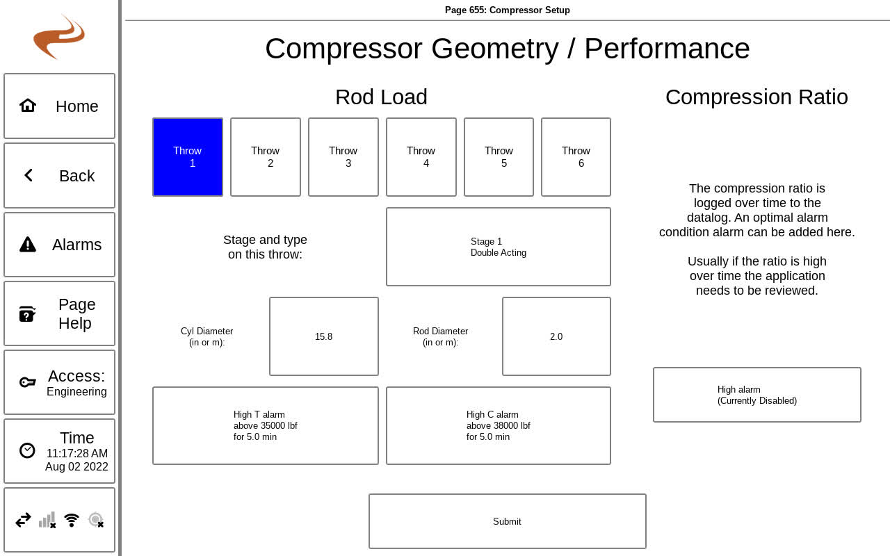
Compressor Geometry Setup
On the left side of the page, the piston sizes can be entered to enable rod load monitoring. For each throw of the compressor enter a cylinder diameter and rod diameter for the compressor piston. Also select what the type of cylinder is. If valid, the system will measure the rod load of each throw over time, in lbf, during tension and compression. High rod loads or unbalanced loads can lead to premature wear or failure of compressor parts. A high alarm can be added to each throw to shut down the engine if a load is exceeded for that stage.
The tension and compression load for each throw will also be added to the normal datalog to be trended over time if desired.
The right side of the page allows an alarm to be added for exceeding a compression ratio. Each stage’s compressor ratio will automatically be logged, and an alarm can be added here to shut down the engine if a stage exceeds the given ratio. Generally a ratio above around 4.5 indicates a design issue with the application.
