DCT Panel Switch Connections: Difference between revisions
m (Thomas Peterson moved page Panel Switch Connections to DCT Panel Switch Connections without leaving a redirect) |
|||
| (8 intermediate revisions by 2 users not shown) | |||
| Line 1: | Line 1: | ||
=== Background === | === Background === | ||
Most panels wire the panel switches to the Brain module - Start, Stop, Reset, Speed Auto, Speed Manual, Speed Increase, and Speed Decrease | |||
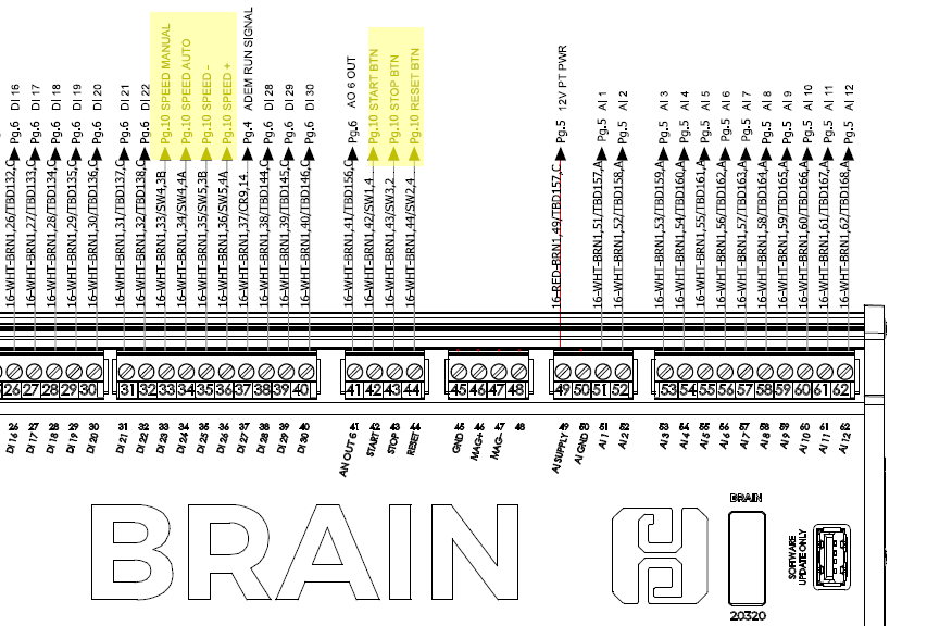
[[File:DCT Panel Switch Connections.png]] | |||
Normal Switch Wiring Locations | ''Normal Switch Wiring Locations'' | ||
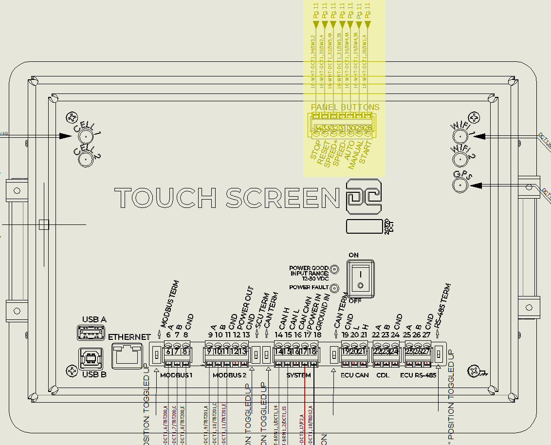
Alternately, a new revision of the DCT adds panel switch wiring to the back of the screen. This allows for less wiring between the inner door and the panel, and frees up the inputs on the Brain to be used for other purposes.[[File:DCT PANEL SWITCH CONNECTIONS (2).png]] | |||
''New Option - Connecting Switches To Screen'' | |||
=== Ordering Information === | === Ordering Information === | ||
| Line 17: | Line 16: | ||
=== Field Swap Implication === | === Field Swap Implication === | ||
Sometimes DCTs will need replacement in existing panels | |||
* Old DCT -> New DCT: OK. The new DCT will work fine in old panels where the switches are wired to the Brain. No settings or other changes are needed, the wiring can be left running to the Brain. | * Old DCT -> New DCT: OK. The new DCT will work fine in old panels where the switches are wired to the Brain. No settings or other changes are needed, '''the wiring can be left running to the Brain'''. | ||
* New DCT -> Old DCT: Not Ok. If a panel has wiring going to the back of the screen and an old DCT is installed there will be nowhere to land the wires. | * New DCT -> Old DCT: Not Ok. If a panel has wiring going to the back of the screen and an old DCT is installed there will be nowhere to land the wires. | ||
| Line 39: | Line 38: | ||
* DCT: 1.53.48 | * DCT: 1.53.48 | ||
* Brain: 2331 | * Brain: 2331 | ||
* EDT : 2027 | |||
[[Category:DCT]] | |||
Latest revision as of 20:07, 29 August 2023
Background
Most panels wire the panel switches to the Brain module - Start, Stop, Reset, Speed Auto, Speed Manual, Speed Increase, and Speed Decrease
Normal Switch Wiring Locations
Alternately, a new revision of the DCT adds panel switch wiring to the back of the screen. This allows for less wiring between the inner door and the panel, and frees up the inputs on the Brain to be used for other purposes.
New Option - Connecting Switches To Screen
Ordering Information
- The new DCT with panel switch connections is p/n 20270-0001
- Usually the DCT will be installed in a new panel with wiring running to the back of the screen so no field changes are needed
Field Swap Implication
Sometimes DCTs will need replacement in existing panels
- Old DCT -> New DCT: OK. The new DCT will work fine in old panels where the switches are wired to the Brain. No settings or other changes are needed, the wiring can be left running to the Brain.
- New DCT -> Old DCT: Not Ok. If a panel has wiring going to the back of the screen and an old DCT is installed there will be nowhere to land the wires.
Settings Changes
In general there won't be any settings differences for either case. If the wires are going to the new DCT, the wires will be detected and the DCT pins will be used. If not, the Brain pins will be used. This process is automatic.
Removing old DI23-26
If the digital input setup is showing the speed switches configured on DI23 - DI26, but switches are wired to the screen, then the old inputs can be freed up by going to Brain -> Output Setup -> Speed control output -> hit next / Submit (without changing anything). When you hit 'Submit' the DCT will detect that the new pins are being used instead and will free up DI23-26.
Switch Timeout Alarm
If the new switch pins on the DCT are in use, then the Brain will expect the switch positions to be always communicated. If the communication times out for more than 60s then an alarm saying "Panel switch information from DCT lost" will be generated and the unit stopped for safety. Since the timeout is 60s, it is ok to power cycle the DCT but it can't be left off very long.
If this alarm triggers unexpectedly it could be because of a CAN connection issue, so the CAN wires and ferrules should be checked.
Software Version Requirements
In order to use the switch pins on the back of the DCT the versions should be at the following or newer:
- DCT: 1.53.48
- Brain: 2331
- EDT : 2027
