Ignition Setup: Difference between revisions
Sean Sanders (talk | contribs) |
No edit summary |
||
| (3 intermediate revisions by 2 users not shown) | |||
| Line 1: | Line 1: | ||
Note: In most cases it will be easier to use Engine Quick Setup under System Settings / Utilities, rather than this long-form ICM setup. | |||
After physical installation and wiring is completed, the ICM must be configured prior to operation. To configure, navigate to the Ignition Setup screen from the ICM home slide Setup -> Main Setup. Security access of Setup or Engineering is required. | |||
=== Step 1: Main Engine Settings === | |||
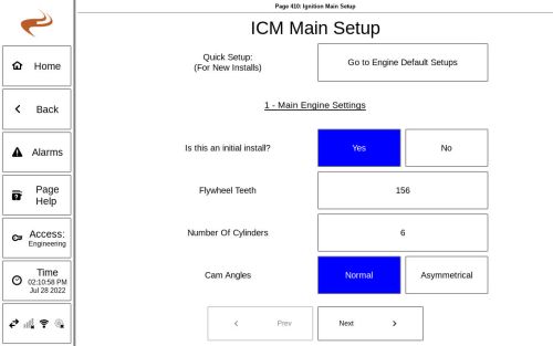
Step 1 of the setup process involves identifying engine parameters and sparking type. | |||
* Initial Install - Select YES if this is a first install | |||
* Flywheel Teeth - Number of teeth on the flywheel for one revolution | |||
* Cylinder Count - Number of cylinders of the engine | |||
* Cam Angles: For most engines, this is "Normal", which signifies that cylinders fire in even gaps. If "Asymmetrical" is selected, then two angles can be specified to configure the ignition to use two opposite angle gaps between cylinders. For example, if the first angle is 60 and the second 120, then the second cylinder will fire 60 (flywheel) degrees after the first cylinder, and the third cylinder will fire 120 degrees after the second cylinder, and so on. | |||
[[File:ICM Main Setup.jpg|500px]] | |||
=== Step 2: Timing Type === | |||
This slide is used to specify what type of inputs are used for position information. | |||
* “Wasted Spark” will fire ignition on both the compression and exhaust strokes | |||
* “Camshaft TDC- Hall Effect” will utilize a Hall effect sensor to indicate the TDC of the compression stroke of the reference cylinder, and does not use a flywheel TDC | |||
* “Camshaft TDC- Magnetic Pickup” will use a magnetic pickup on the cam to indicate TDC of the compression stroke, with the MPU plugged into the “Flywheel TDC Index Mag Pickup” port (though in reality there is no flywheel TDC sensor) | |||
* “Cam Timing disc hall/MPU”- will use a magnetic pickup or hall (depending on option selected) on a cam timing disk to sense the camshaft position. This timing disk will have one mark (gap or magnet) for the TDC of each cylinder, and one extra mark to indicate the reference cylinder. This mode is often used if a digital ignition was already installed. If using a timing disc but the layout is unknown, choose an option and use the "Timing Disc Test" page after completing setup. | |||
=== Step 3: Cylinder Firing Order === | |||
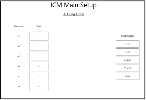
This step is used to define the engine firing order for the number of cylinders defined in Step 1. Use the number keypad on the right to set the cylinder number to the firing order. The firing order can usually be found on the engine block. | |||
[[File:Icm-firing-order.PNG|500px]] | |||
If needed, cylinders can be appended with “L” and “R” letters for left and right banks. If utilizing the “L” and “R” designations, all cylinders should include either an “L” or an “R”. | If needed, cylinders can be appended with “L” and “R” letters for left and right banks. If utilizing the “L” and “R” designations, all cylinders should include either an “L” or an “R”. | ||
| Line 39: | Line 32: | ||
If applicable, a pre-defined engine can be selected on the right side of the screen to fill in the firing order. | If applicable, a pre-defined engine can be selected on the right side of the screen to fill in the firing order. | ||
=== Step 4: Harness Information === | |||
=== | |||
Step | |||
Use the “Harness P/N” box to select the harness part number. The part number can be found on the tag attached to the coil harness. This is used to determine the wire colors. | |||
Use the “Harness” buttons to toggle between “Harness 1” and “Harness 2” if the installation required two ignition coil harnesses. Use the wire boxes to identify what colored wire is connected to each cylinder. The harnesses are labeled at the connector on the printed circuit board internal to the ICM enclosure. | |||
Note that usually the default order is already filled in. | |||
If the ICM8 was installed, which only supports up to eight cylinders, the harness 1/2 option buttons will not be shown. | |||
=== | === Step 5: Setup Review === | ||
Step 5 is used to review the setup configuration. | Step 5 is used to review the setup configuration. | ||
If the information is correct, press the “Setup Complete” button. If not, press the “< Back” button to modify the settings. | If the information is correct, press the “Setup Complete” button. If not, press the “< Back” button to modify the settings. | ||
Latest revision as of 15:57, 4 August 2022
Note: In most cases it will be easier to use Engine Quick Setup under System Settings / Utilities, rather than this long-form ICM setup.
After physical installation and wiring is completed, the ICM must be configured prior to operation. To configure, navigate to the Ignition Setup screen from the ICM home slide Setup -> Main Setup. Security access of Setup or Engineering is required.
Step 1: Main Engine Settings
Step 1 of the setup process involves identifying engine parameters and sparking type.
- Initial Install - Select YES if this is a first install
- Flywheel Teeth - Number of teeth on the flywheel for one revolution
- Cylinder Count - Number of cylinders of the engine
- Cam Angles: For most engines, this is "Normal", which signifies that cylinders fire in even gaps. If "Asymmetrical" is selected, then two angles can be specified to configure the ignition to use two opposite angle gaps between cylinders. For example, if the first angle is 60 and the second 120, then the second cylinder will fire 60 (flywheel) degrees after the first cylinder, and the third cylinder will fire 120 degrees after the second cylinder, and so on.
Step 2: Timing Type
This slide is used to specify what type of inputs are used for position information.
- “Wasted Spark” will fire ignition on both the compression and exhaust strokes
- “Camshaft TDC- Hall Effect” will utilize a Hall effect sensor to indicate the TDC of the compression stroke of the reference cylinder, and does not use a flywheel TDC
- “Camshaft TDC- Magnetic Pickup” will use a magnetic pickup on the cam to indicate TDC of the compression stroke, with the MPU plugged into the “Flywheel TDC Index Mag Pickup” port (though in reality there is no flywheel TDC sensor)
- “Cam Timing disc hall/MPU”- will use a magnetic pickup or hall (depending on option selected) on a cam timing disk to sense the camshaft position. This timing disk will have one mark (gap or magnet) for the TDC of each cylinder, and one extra mark to indicate the reference cylinder. This mode is often used if a digital ignition was already installed. If using a timing disc but the layout is unknown, choose an option and use the "Timing Disc Test" page after completing setup.
Step 3: Cylinder Firing Order
This step is used to define the engine firing order for the number of cylinders defined in Step 1. Use the number keypad on the right to set the cylinder number to the firing order. The firing order can usually be found on the engine block.
If needed, cylinders can be appended with “L” and “R” letters for left and right banks. If utilizing the “L” and “R” designations, all cylinders should include either an “L” or an “R”.
If applicable, a pre-defined engine can be selected on the right side of the screen to fill in the firing order.
Step 4: Harness Information
Use the “Harness P/N” box to select the harness part number. The part number can be found on the tag attached to the coil harness. This is used to determine the wire colors.
Use the “Harness” buttons to toggle between “Harness 1” and “Harness 2” if the installation required two ignition coil harnesses. Use the wire boxes to identify what colored wire is connected to each cylinder. The harnesses are labeled at the connector on the printed circuit board internal to the ICM enclosure.
Note that usually the default order is already filled in.
If the ICM8 was installed, which only supports up to eight cylinders, the harness 1/2 option buttons will not be shown.
Step 5: Setup Review
Step 5 is used to review the setup configuration.
If the information is correct, press the “Setup Complete” button. If not, press the “< Back” button to modify the settings.

