DCT Basic Navigation: Difference between revisions
No edit summary |
|||
| Line 53: | Line 53: | ||
[[File:Access.jpg]] | [[File:Access.jpg]] | ||
If the system is in ‘Key Required’ mode, while the key is in the different levels can be accessed normally. With the key removed, the ‘Engineering’ password will not work. | If the system is in ‘Key Required’ mode, while the key is in the different levels can be accessed normally. With the key removed, the ‘Engineering’ password will not work. | ||
As an alternate to the standard passwords or the USB key, the passwords can be managed remotely if EMIT telematics is used. See [[Region Passwords]]. | |||
=== Settings Navigation === | === Settings Navigation === | ||
Latest revision as of 13:26, 1 October 2024
The EMIT Dynamic Control Touchscreen provides a 12” display and communication hub for any one module, or multiple modules, connected to the Controller Area Network (CAN) of the screen. Modules connected to the CAN port will automatically be displayed as ‘tabs’ on the system home screen of the display. Selecting any of the module buttons allows for current status of that module.
Other functions not directly related to module interaction include the system run signal trigger, security passwords and access, timer management, alarms, date and time, sensor data logging, and MODBUS communications.
The touchscreen is designed to be mounted directly into panel face.
User Interface Overview
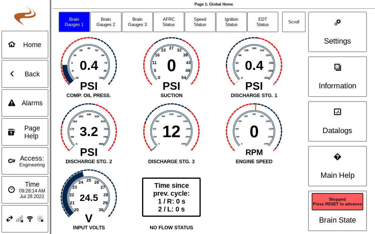
An example of the home page is shown below
Page Number and Title
The top of the page shows the page number and title of the page.
Sidebar
The sidebar is always present on the left side of the screen. The following buttons are in the sidebar:
- Home: Always returns to the system home screen. (Shown in the example)
- Back: Returns to the previous page
- Alarms: Views current active alarm events and old acknowledged alarm events. Additionally, logs of recent shutdowns can be viewed.
- Page Help: Will show a popup with help for the current page, if available.
- Access: Shows the current access level, and shows a keypad for entering a password. Higher access levels allow for more settings changes.
- Time: Shows the current time, and navigates to a screen for setting the time and viewing expired timers. If a timer is expired the icon will flash.
- Connection Status: Shows the status of the CAN, Wifi, Cell, and GPS signals. Selecting the button navigates to the connection information page.
The home page will show ‘tabs’ along the top for connected modules. The Brain (core) module, if attached, can have multiple tabs.
Selecting a tab or swiping the central area will change between status slides for each module. For the Brain module gauges (e.g. Suction pressure, Oil Temperature) the gauge can be selected to see more information for that input.
The ‘Settings’ button on the Home page navigates to the settings menu to access settings for all modules.
The ‘Datalogs’ button will navigate to the datalog display page to view long term datalogs for any sensor.
The ‘Information’ button will navigate to the Information menu which leads to various informational items for different parts of the system.
The bottom-right button of the Home page will show the current Brain module state. Selecting the button will navigate to more status information for that module. This page will be discusses in a later section.
Access Levels
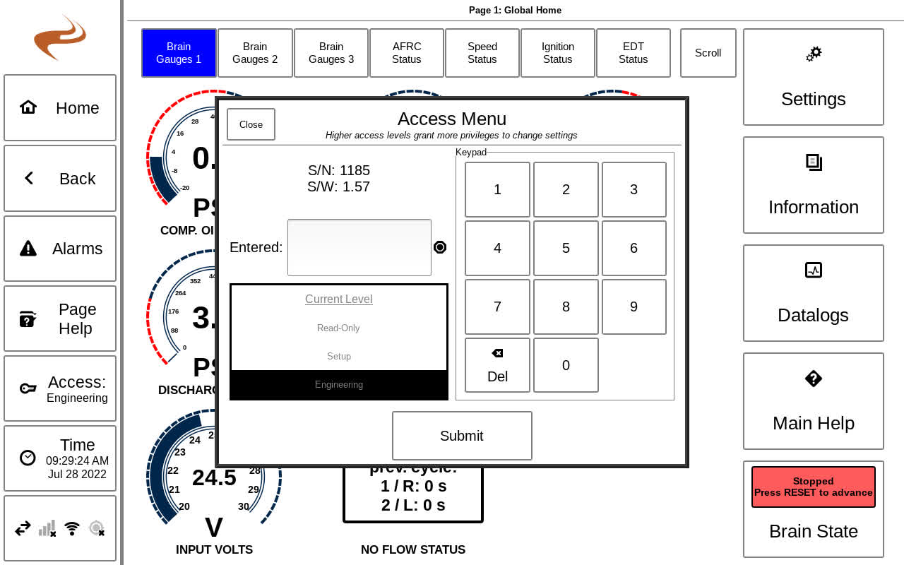
The active security access is displayed in the “Access:” button in the sidebar. To change the security access mode, select the “Access:” button and input the password of the desired security using the keypad. Available security levels include:
- Read-Only – Limited access to system features. No adjustments can be made.
- Setup – Access to most system features and settings.
- Engineering – Access to all system features including advanced adjustments.
When shipped, the passwords will be attached to a tag on the back of the unit. Type in the password in the dialog and select ‘Submit’ to enter the new level. Optionally, a USB security key can be purchased that allows for the touchscreen to be changed to ‘Security Key Required’ mode. In this mode, the USB security key must be inserted to access engineering access level, while the Setup level will still be accessed with a normal password. The key itself is also used to set or clear the key required setting.
If the system is in ‘Key Required’ mode, while the key is in the different levels can be accessed normally. With the key removed, the ‘Engineering’ password will not work.
As an alternate to the standard passwords or the USB key, the passwords can be managed remotely if EMIT telematics is used. See Region Passwords.
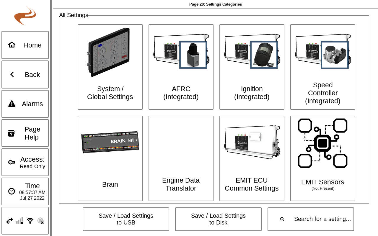
The ‘Settings’ button on the Home screen can be selected to navigate to the Settings Categories Menu, shown below.
Each module is shown as a category, so selecting that module will navigate to the module settings menu. The ‘System / Global Settings’ button navigates to settings options that are not limited to one particular module. Options under that menu are covered in the next section.
The Settings Categories page also has three utility buttons:
- Save / Load Settings to USB: This page can be used to save and load settings off a flash drive for backup purposes or to use on another unit. See DCT Config Files
- Save / Load Settings to Disk: This page can be used to make backups of unit settings at particular times, in case settings need to be rolled back in the future.
- Search for a setting...: Because there are many settings on the system, this page can be used to quickly find a setting instead of navigating through normal menus. Simply type a keyword or title of the setting and potential matches will appear on the right.

