Annunciator Setup - Custom PID: Difference between revisions
Sean Sanders (talk | contribs) |
No edit summary |
||
| Line 1: | Line 1: | ||
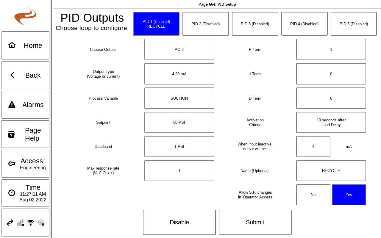
The | The Brain supports up to five custom PID analog outputs. These outputs can be used to control a variety of processes and controls. A PID output can be configured on the PID Setup Screen by navigating from the main setup to “Outputs Setup” then “Custom PID”. | ||
Note: Only experienced personnel should adjust PID settings | Note: Only experienced personnel should adjust PID settings | ||
| Line 7: | Line 7: | ||
''PID Setup Screen'' | ''PID Setup Screen'' | ||
To configure a PID output, select one of the | To configure a PID output, select one of the available PID loops at the top of the screen. Each setting is outlined below. When complete, select “Submit” to save, or “Disable” to disable that PID loop. | ||
*Choose Output: Select this button to choose the analog output to use. All available analog outputs will be listed to select. | |||
*Output Type: Choose 4-20mA, 1-5V, or 0-5V based on what equipment is driven | |||
*Process Variable: Choose the process variable. This is the variable that will react to changes in the output. | |||
*Setpoint: Choose the target setpoint for the process variable. | |||
*Deadband: Choose a deadband for the setpoint. Within this deadband around the setpoint, the output will not be changed | |||
*Max response rate: The max response rate is the percentage of the output range that will be changed in one second when the controller is moving at its fastest rate. This clips the change in controller output after the loop calculates the value. | |||
*P,I,D term: These are the actual Kp,Ki,Kd constants | |||
*Activation Criteria: Select this button to choose when the loop should be active. | |||
*Inactive state: Enter what the output should be when the controller is not active | |||
=== PID Status and Auto / Manual Control === | === PID Status and Auto / Manual Control === | ||
Under the " | Under the "Faults / Outputs Status page" reached by hitting the "Brain State" button of the home page, there is a PID category to view the PID status. | ||
[[File:Pid-status-overview.png]] | |||
Selecting a loop will navigate to the PID Status Page for that single loop, shown below. | Selecting a loop will navigate to the PID Status Page for that single loop, shown below. | ||
[[File:Pid-status-single.png]] | |||
On this page, the mode "Auto" or "Manual" can be selected if the access level is 'setup' or higher. In manual, the box on the right side of the page will show the manual setting, and can be selected to change the output. | On this page, the mode "Auto" or "Manual" can be selected if the access level is 'setup' or higher. In manual, the box on the right side of the page will show the manual setting, and can be selected to change the output. | ||
=== PID status gauge === | |||
Optionally a gauge can be added to the home screen to show the status of a PID loop. The gauge will show the current input and output values, and selecting the gauge will go to the single loop status page shown in the previous section. | |||
See [[Annunciator Setup - Home Page Gauges]] for gauge setup, and the PID status gauges are under the "Other" category. | |||
Revision as of 21:34, 4 August 2022
The Brain supports up to five custom PID analog outputs. These outputs can be used to control a variety of processes and controls. A PID output can be configured on the PID Setup Screen by navigating from the main setup to “Outputs Setup” then “Custom PID”.
Note: Only experienced personnel should adjust PID settings
PID Setup Screen
To configure a PID output, select one of the available PID loops at the top of the screen. Each setting is outlined below. When complete, select “Submit” to save, or “Disable” to disable that PID loop.
- Choose Output: Select this button to choose the analog output to use. All available analog outputs will be listed to select.
- Output Type: Choose 4-20mA, 1-5V, or 0-5V based on what equipment is driven
- Process Variable: Choose the process variable. This is the variable that will react to changes in the output.
- Setpoint: Choose the target setpoint for the process variable.
- Deadband: Choose a deadband for the setpoint. Within this deadband around the setpoint, the output will not be changed
- Max response rate: The max response rate is the percentage of the output range that will be changed in one second when the controller is moving at its fastest rate. This clips the change in controller output after the loop calculates the value.
- P,I,D term: These are the actual Kp,Ki,Kd constants
- Activation Criteria: Select this button to choose when the loop should be active.
- Inactive state: Enter what the output should be when the controller is not active
PID Status and Auto / Manual Control
Under the "Faults / Outputs Status page" reached by hitting the "Brain State" button of the home page, there is a PID category to view the PID status.
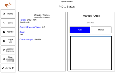
Selecting a loop will navigate to the PID Status Page for that single loop, shown below.
On this page, the mode "Auto" or "Manual" can be selected if the access level is 'setup' or higher. In manual, the box on the right side of the page will show the manual setting, and can be selected to change the output.
PID status gauge
Optionally a gauge can be added to the home screen to show the status of a PID loop. The gauge will show the current input and output values, and selecting the gauge will go to the single loop status page shown in the previous section.
See Annunciator Setup - Home Page Gauges for gauge setup, and the PID status gauges are under the "Other" category.

