ECU Connector Pinouts
From EMIT Controls
Module Pins
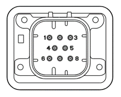
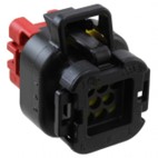
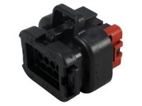
The ECU module has five connections, which are (from left to right) Ignition, Injection, Main Engine, Panel, and Exhaust. The plugs are keyed and colored so that same size plugs cannot be plugged into each other. Pin numberings for each are shown below.
Ignition Connector - 8 Pins
| Pin | Connection |
|---|---|
| 1 | Coil 1- |
| 2 | Coil 2 - |
| 3 | Coil 3 - |
| 4 | Coil + (all coils) |
| 5 | Shield |
| 6 | Coil 4 - |
| 7 | Coil 5 - |
| 8 | Coil 6 - |
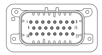
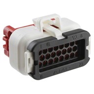
Main Engine Connector - 23 Pins
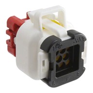
This is the white 23-pin connector.
Note: Numbers in parentheses under “Connection” below are the destination plug pin label.
| Pin | Connection |
|---|---|
| 1 | Oil Thermistor + (1) |
| 2 | Oil Thermistor – (2) |
| 3 | Throttle + (4) |
| 4 | Throttle – (1) |
| 5 | Throttle position 1 (6) |
| 6 | Throttle position 2 (5) |
| 7 | MPU TDC+ / Hall (*) |
| 8 | MPU TDC- (*) |
| 9 | Coolant Thermistor + (1) |
| 10 | Coolant Thermistor – (2) |
| 11 | DPV A (A) |
| 12 | DPV D (D) |
| 13 | Solenoid + |
| 14 | Throttle pot ground (*) |
| 15 | Shield (*) |
| 16 | Oil Pressure Sig (C) |
| 17 | Manifold pressure Sig (C) |
| 18 | 12V Power for hall (*) |
| 19 | DPV B (B) |
| 20 | DPV C (C) |
| 21 | Motor pot 5V (*) |
| 22 | Flywheel MPU + (A) |
| 23 | Flywheel MPU – (B) |
*These connections at the sensor vary numbering by engine or branch to multiple locations. See engine harness drawing.
Panel Connector - 23 pins
This is the black 23 pin connector
(Physical pin layout the same as the image in main engine section above)
| Pin | Connection |
|---|---|
| 1 | CAN H |
| 2 | CAN L |
| 3 | CAN GND |
| 4 | Shutdown input (Ground to shut down) |
| 5 | Alarm output |
| 6 | Fuel relay (low drive) |
| 7 | Digital in 2 |
| 8 | Digital in 1 |
| 9 | Battery - |
| 10 | Battery - |
| 11 | Battery - |
| 12 | (Reserved) |
| 13 | 12V sensor power |
| 14 | Analog ground |
| 15 | Analog ground |
| 16 | Battery + |
| 17 | Battery + |
| 18 | Battery + |
| 19 | (Reserved) |
| 20 | (Reserved) |
| 21 | Analog out 1 |
| 22 | Analog in 2 |
| 23 | Analog in 1 |
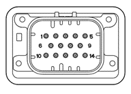
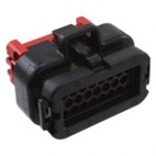
Exhaust Connection - 14 pin
| Pin | Connection |
|---|---|
| 1 | Knock Left |
| 2 | Precat TC + (yellow) |
| 3 | Precat TC - (Red) |
| 4 | Postcat TC + (yellow) |
| 5 | Postcat TC - (Red) |
| 6 | Precat O2 Htr - (C) |
| 7 | Postcat O2 Htr - (C) |
| 8 | Precat O2 Vs (B) |
| 9 | Postcat O2 Vs (B) |
| 10 | Knock Right |
| 11 | Precat O2 Htr + (D) |
| 12 | Postcat O2 Htr + (D) |
| 13 | Precat O2 Vref (A) |
| 14 | Postcat O2 Vref (A) |
