Annunciator Setup - Speed Control
If an EMIT speed controller is not used on the engine, the annunciator can control speed through an analog output connected to the ECU or another governor that uses an analog input to control the speed setpoint. Whether or not the speed output is used, an idle permissive condition can also be added to control a digital output to hold the engine at idle. Either page is accessed from the main annunciator setup by selecting “Outputs Setup” followed by “Speed Control Output” or "Idle Hold Condition". The speed control output setup consists of three pages. The idle hold setup is one page.
Functionality Overview
The idle hold and speed target output work independently, either or both can be used with an ECU.
For idle hold, a condition will be specified where the engine will not be allowed out of idle until the condition is met. For example, a lubricant temperature might be required to be above certain temperature before the engine can go to full speed. Setting up the idle hold condition is shown in the next section. When the idle hold is active, a chosen digital output will be ON. This output is typically wired to a relay and then the output of the relay to an ECU input that keeps the engine at idle. For an ADEM, this input is called "IDLE / RATED SPEED". This output can also be wired to an Idle Permissive lamp. The idle hold can also be used if an EMIT Governor is present, and an annunciator sensor is desired as the controlling sensor.
For speed control target, an analog output will be used to specify the target speed. The ECU will interpret this signal as some speed the engine should be operating and will run accordingly. This target can be based upon a sensor condition, or can be fixed to one speed. Optionally, IDLE/AUTO/MANUAL and SPEED+/- switches can be wired to the annunciator to function similarly to the EMIT governor. In other scenarios, an AUTO/MANUAL switch can be used to physically disconnect the speed signal and connect it to a potentiometer on the ECU panel.
Idle Hold Setup
The idle hold setup is shown on the following page. (Note: On some older versions, this was on the first page of speed control setup, but the options are the same).
To specify an idle hold condition, select “Yes” for using idle hold. If desired, select an output pin that will be ON during idle hold. Select the second button to specify the sensor and condition which will define the idle hold.
During idle hold, the annunciator will perform the following three actions:
- If an EMIT speed controller is present, it will send a message to the governor to remain in idle
- If specified, the annunciator will turn ON the digital output configured
- If using speed control output (remaining part of this page), the annunciator will send the idle speed setpoint on the analog out used
The digital output can be used to light a lamp, and/or to connect to an idle pin (such as the Caterpillar IDLE/RATED SPEED input). This is optional in some cases (such as 1 or 3 above).
Speed Control Setup 1
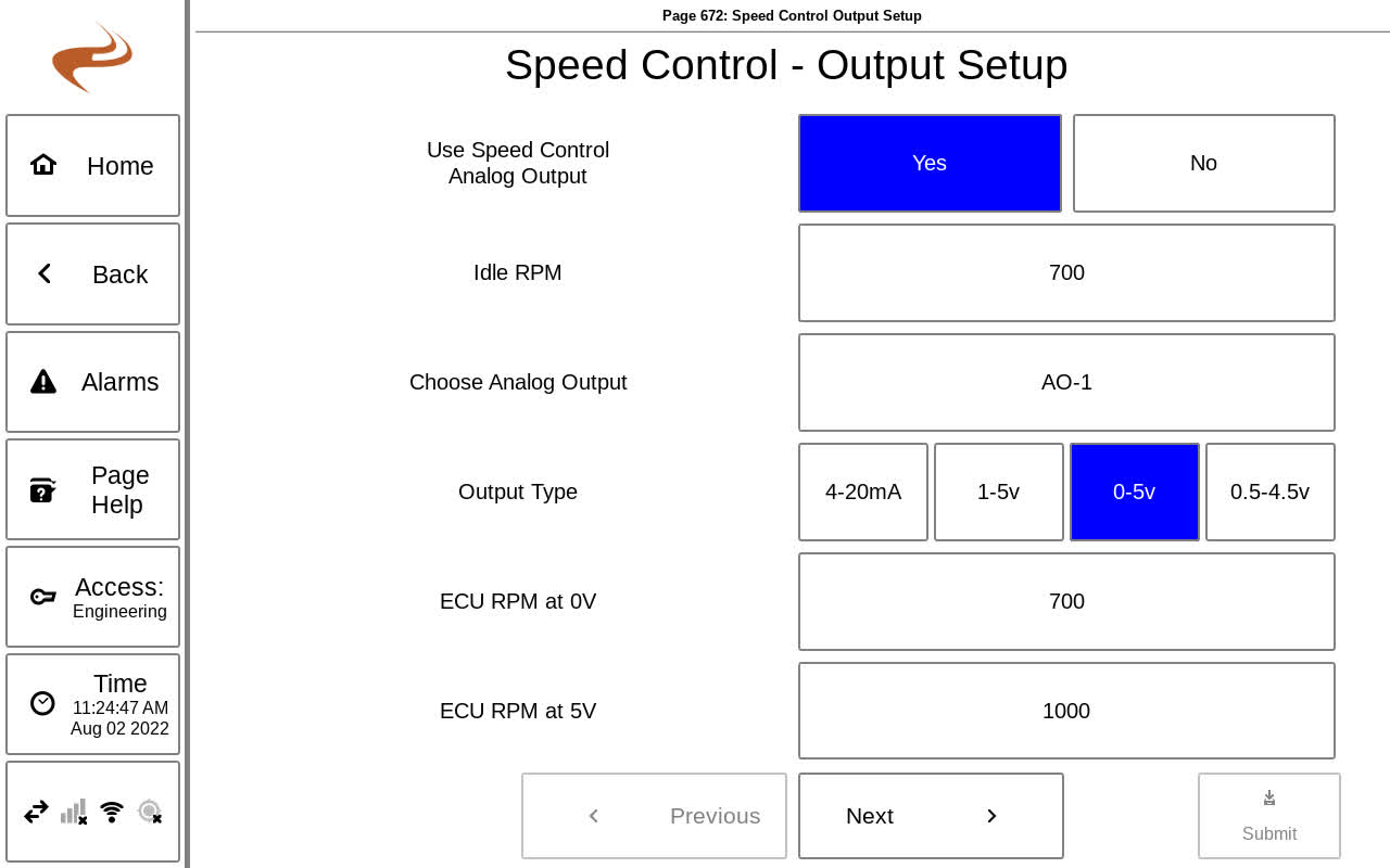
The first page of speed control output setup is shown below. This page sets up the electrical settings of the output.
If using an analog output for speed setpoint, select "Yes" on this page to begin setup.
If an EMIT governor is present in the system, the next line can be selected to send the target to the module. (Note: The speed control settings can alternately be set up in the Governor section of the EIM in this case. However, it might be preferred so set it up in the annunciator, since the annunciator has access to more sensors than the governor).
If using DI-23 to DI-26 for speed control switches, select "Yes" on that line, and enter an idle rpm for when the switch is at "Idle". This idle RPM will also be used when the idle hold condition is active, if used. If not using DI-23 to DI-26 for speed control switches, the idle speed is not available, because it will be set on the external ECU.
The next button can be selected to choose an output for the speed setpoint. All available outputs are shown, including expansion modules. This output will be wired to the ECU or Governor at the speed control input.
The 'output type' selection is for the output type of the analog output. The options are 4-20mA, 1-5V, 0-5V, and 0.5-4.5V. The selection should match what the ECU or Governor speed input is expecting. CAT panels generally expect 0.5V to 4.5V.
The last two settings are the low and high speed values when the ECU or Governor speed input is at its limits. These values are based on what the ECU or Governor expects, and the RPM values don’t necessarily have to ever be reached. On some ECUs these values match idle speed and overspeed.
Speed Control Setup 2
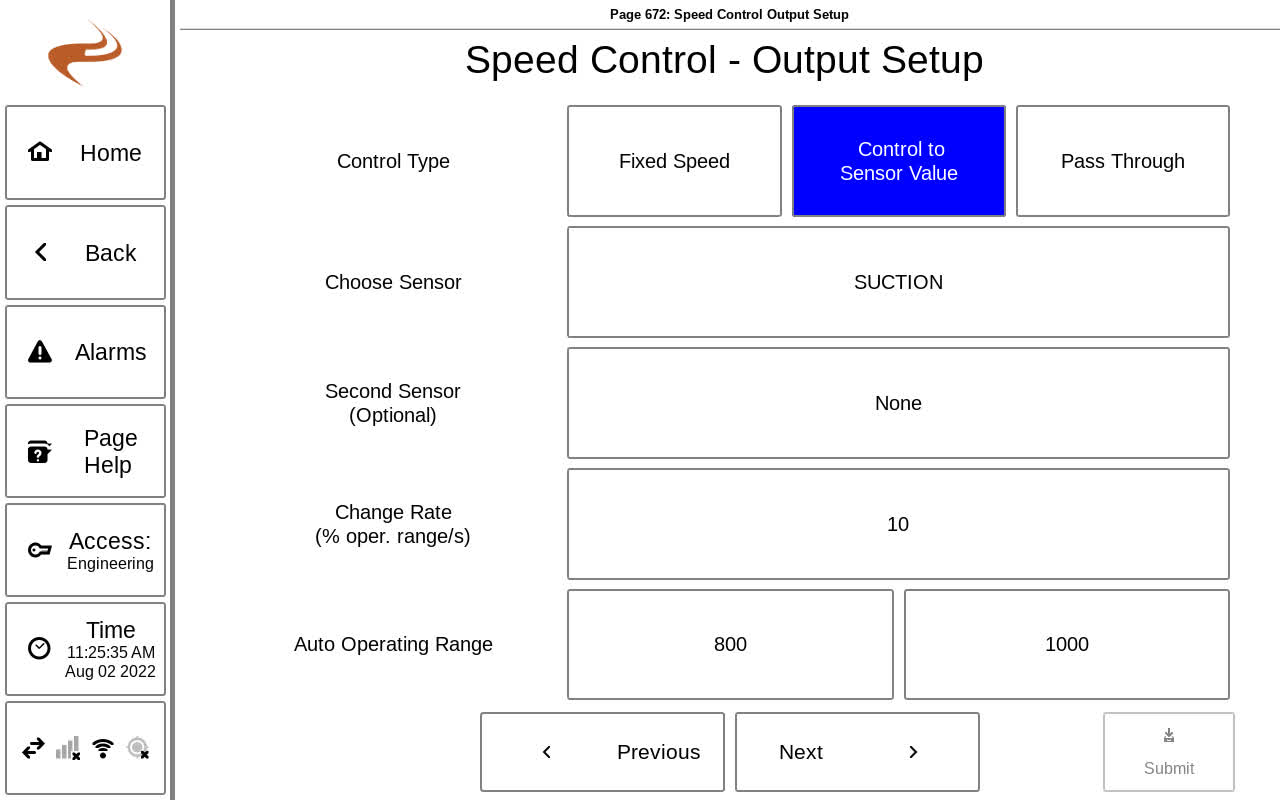
The second page for speed control setup configures the actual control settings for the speed.
Speed Control Output Setup 2
The control type can be either “Fixed Speed”, “Control to Sensor Value”, or "Pass Through". If fixed speed is used, the only other setting needed is the speed setpoint. In this case, the annunciator will simply output a fixed analog value to keep the speed at this point. If "Pass Through" is used (which is not common), the annunciator will pass an analog input to the analog output.
If controlling to a sensor value, more settings are available, which are outlined below.
- Choose Sensor: Select this button to choose the sensor the speed is controlling around. If this sensor is too low or high the speed will be adjusted. Most commonly this will be suction or final discharge pressure.
- Sensor Control Type: (Requires EIM 2.00 and Annunciator 822 or newer) For "Setpoint/Deadband", the system will increase or decrease speed if the sensor is out of the range setpoint +/- deadband, until reaching the edge of the operating range. If the sensor value is within the setpoint +/- deadband, the speed target will not be changed. For "Linear Ramp" type control, the speed target will be determined based on the value of the sensor within the range Low Setpoint - High Setpoint. For example, if the sensor is in the middle of Low<->High setpoint, the speed target will be the middle of operating range.
- Setpoint (SP/DB type only): This is the target value for the sensor chosen. For some types of sensors, such as discharge or manifold, this setpoint should be held fairly close. For some, such as suction, the speed will spend a lot of time near the limits and the setpoint is more of a cross-over point when the sensor goes from high/low or low/high.
- Deadband (SP/DB type only) : The deadband defines a region around the setpoint where the speed will not change.
- Low Setpoint (Linear Ramp type only): The low setpoint for the process sensor
- High Setpoint (Linear Ramp type only): The low setpoint for the process sensor
- Change Rate: The change rate defines the percentage of the operating range that the rpm will swing in one second. For example, if set to 50% then it will take two seconds to ramp from the low to the high range if required. Setting to a lower value will slow down the control. Suction control will usually be in the 1-5% range to cause slow changes, and discharge control will be higher, generally 10-20%.
- Positive or Negative Control: This setting controls the direction the speed will change to meet the target setpoint. For positive control, increasing the RPM will increase the sensor, such as manifold or discharge pressure. For negative control, increasing the RPM will decrease the sensor, such as suction pressure.
- Auto Operating Range: This defines the operating RPM range for the speed output. If the output reaches one of these limits and the sensor is still out of setpoint range, the RPM will be clamped to this value. These limits keep the engine from going too fast or slow when trying to meet the setpoint.
After reviewing the entered settings, select “Submit” to save.

