Annunciator Basic Setup and Configuration Overview
From EMIT Controls
There are a large number of Brain setup screens, all accessed through Settings -> Brain and its subpages.
Basic Input Setups
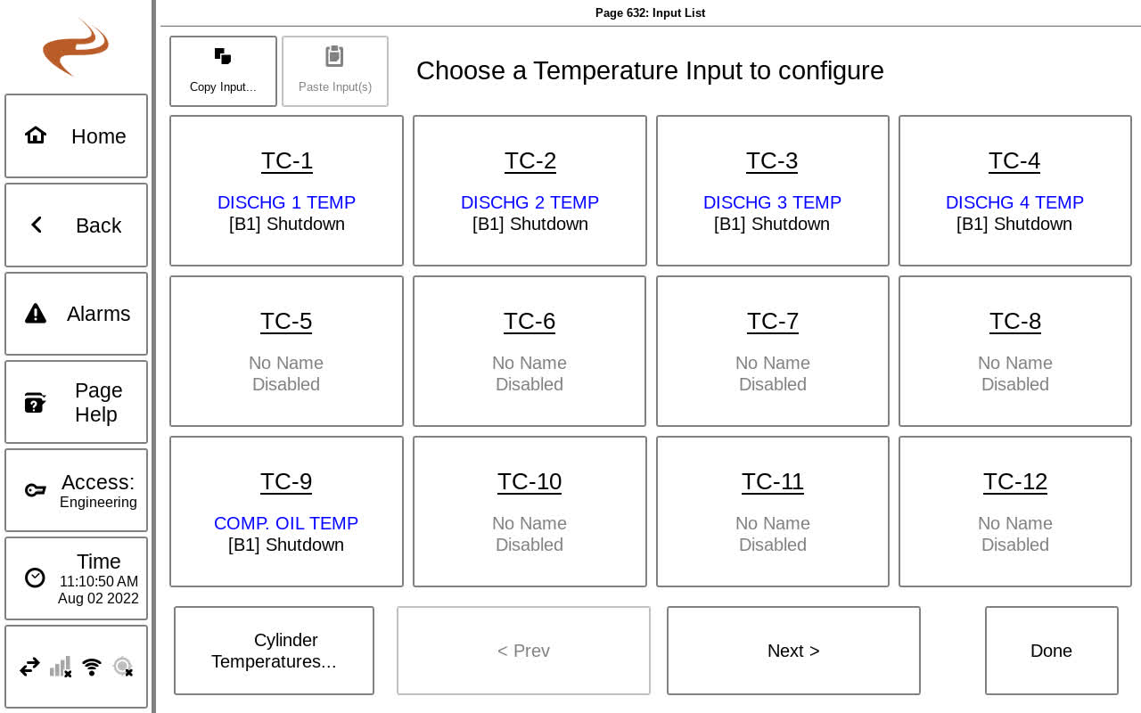
The basic four types of inputs (Analog, Digital, Thermocouple, and Magnetic Pickup) are setup through “Brain Setup” then “Inputs Setup”. For the first three types mentioned, selecting the input category will show a list of available inputs, and one can be selected to configure. Details on the setup items of each is listed below.
Digital Inputs
- Name: Choose or type in a name for the input
- Type: Choose normally open or normally closed, based on the sensor type
- Newer Brain versions also allow a detect loop option, see Digital Inputs Detect Loop
- Alarm action and class: Choose as needed based on the descriptions in the overview section
Analog Inputs
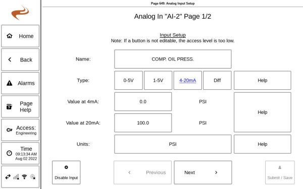
- Name: Choose or type in a name for the input
- Type: Choose 0-5V, 1-5V, 4-20mA, diff based on the sensor type
- For "diff" type, see Annunciator Dual Sensor Differential Inputs
- Value at (low) and (high): Enter the full range of the sensor. This should be printed on the sensor itself or can be found in the sensor documentation.
- Units: Enter the unit of the sensor for when displaying the value
- Note: If an EMIT governor is on the system and pressure-based speed control is used, the suction/discharge sensors on the Brain must use the units “PSI” or “KPA”.
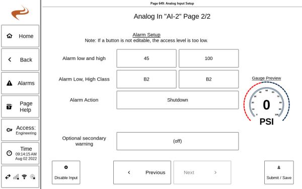
- Alarm low and high: Enter the low and high alarm for the sensor. If either the low or high is not needed, it can be put at the limit or out of range of the sensor to keep it from faulting.
- Alarm action and class: Choose as needed based on the descriptions in the overview section
- Optional secondary warning: If an extra warning is desired, it can be added here.
Thermocouples
- Name: Choose or type in a name for the input
- Type: Choose Type K or Type J based on the thermocouple type
- Alarm low/ high: Choose the low and high alarms if required. An unneeded limit can be set to zero to be disabled.
- Alarm action and class: Choose as needed based on the descriptions in the overview section
- Optional secondary warning: If an extra warning is desired, it can be added here.
Input Setup Example- Thermocouple
Magnetic Pickup
- Type: Choose MPU for a normal MPU input, or Analog for using an analog input as a speed reference (e.g. from a VFD)
- Number of flywheel teeth: Enter the number of teeth expected on the MPU. This can be "0" if a physical MPU is not used and the RPM value is coming from the engine data translator.
- Low/high alarm values: Enter limits as required. The low limit can be set to ”0” if not needed.


