Troubleshooting
DCT
Display will not power on
- Try cycling power on the screen
- Verify that the input voltage is between 12 and 30 VDC
- If input power is good but the green power LED does not come on, the DCT needs repair
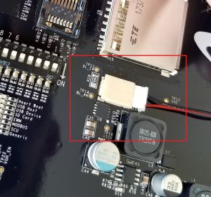
- Behind back cover, verify that the backlight connection is in all the way
- If all of the above is ok and there is still no boot, the DCT needs repair.
Does not call out alarms
- Verify that the screen is activated
- Select the connection information in the lower left corner of the screen. The bottom right box should show that service is activated
- Does the DCT have a cell connection at all?
- This would show on the screen in the lower left
- If not connected, it might need a power cycle
- If connected recently, it might have poor signal strength and need a directional antenna
- If not working at all, it may be a bad modem or poor service area
- If poor service area, possibly the modem could be changed to verizon or changed to satellite
- Check that callouts are enabled under global settings - Telematics
- Check that contacts are assigned under the unit on the connect site
Brain / Annunciator / Brain+ 20320 20330
Input Issues
4-20 mA Analog input issues
- Verify that the input setup is correct for 4-20mA vs 0-5V.
- Check the voltage to ground at the input pin on the annunciator module. It should be roughly 1-5 Volts DC. If it is, check the raw value on the annunciator input stats at “Annunciator Setup” -> “Inputs Status” -> “Analog inputs”. If the raw value is showing 0, the board may have an issue.
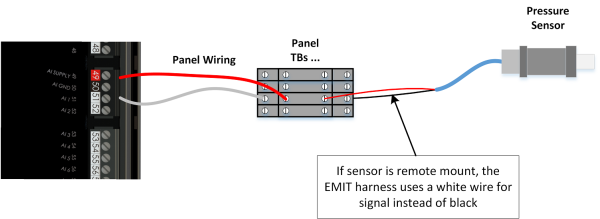
- If there is no voltage at the input pin, check the voltage at the double level terminal block where the sensor is wired. The top level (power) should be at +12V to ground, and the bottom level should be around 1-5v. If the bottom level is at near 12V, there is probably a connection break between the terminal block and the module.
- Sensors should have the red wire to the top level and the black wire to the bottom level. If remote mounted using EMIT harnesses, the bottom level (signal) wire will be white instead of black.
- If the sensor still does not work, try wiring to another input to see if the input itself is bad
0-5V or 1-5V analog input issues
- Verify that the input setup is correct for 0-5v vs 1-5v vs 4-20mA
- Make sure the sensor has the correct supply voltage, looking up specs if needed. Many 1-5v sensors need a 5v supply instead of 12v.
- Check to see if there is 0-5v DC at the annunciator input pin. If not, check the DC voltage at the terminal block.
- If there is no voltage at the block, make sure the other sensor wiring is correct and the sensor is working
- If there is voltage at the TB but not the annunciator, check for wiring breaks or miswiring between the TB and annunciator
Thermocouple inputs reading incorrectly
- Check the cold junction by jumping an input with a short wire jumping a TC+ to TC-. The input should read ambient. If not, check on several other inputs. If all read incorrectly, the cold junction is damaged. If only one reads incorrectly (or one group) those TC inputs have a hardware problem.
- If the TC inputs only read poorly when the engine/motor is running, it is likely a noise issue. Try:
- Running the TC wires away from other wires, and use one conduit or cordgrip for TCs only
- Use TCs with a coating over the armor so that the armor cannot contact ground
- Make sure the panel itself is well grounded to earth
- Verify that the TC type (J vs K) is correct on the panel and matches the actual thermocouples
- Verify that the red and yellow (or red and white) wires are not swapped.
- If a gauge shows the correct reading in the center but it is off the range of the outside gauge, the “display range” of the TC setup needs to be changed.
Digital input reading incorrectly
- Unplug the digital input in question and manually ground/unground the pin. On the annunciator input status*, the pin should go faulted and unfaulted. If not, the input is likely bad.
- Verify that the setting normally open vs closed is correct on the EIM/DCT.
- If First step passes passes, plug the phoenix block back in and try the same test at the terminal block for that input (disconnecting the skid-end of the input). If the input works from there, the problem is on the skid side. If it does not, the problem is in the panel wiring between the terminal block and the module.
* This page is found by hitting the "Brain State" in the lower right of the home page of the DCT, or the left box of the Annunciator home page on the EIM.
Switch input(s) reading incorrectly
- Each switch input is either open or closed to ground. For Start, Reset, and speed switches, all of the blocks are normally open. For stop, the block is normally closed.
- Check continuity at the pins to ground while pressing the switches (pins 42,43,44). Start and reset should have continuity to ground only while switch is pressed. Stop should have continuity to ground only while not pressed.
- If not, check continuity to the white-wired side of the switch block to the annunciator. Then, verify that the other side has continuity to the panel ground.
- Using “Go to page” -> “83” can be used to verify the switch inputs as the annunciator reads them.
MPU input reading incorrectly
- If a governor, EDT, or ignition is present, it is likely that the MPU reading is coming from one of those modules and should be troubleshot from there. If the MPU is physically wired to annunciator pins 46/47, continue to the next line below.
- Make sure that the correct number of flywheel teeth is set on “annunciator setup” -> “Inputs setup” -> “Mag Pickup (RPM) Input”
- Unplug the MPU and use a multimeter to measure AC Volts across the two MPU wires while cranking. It should show around 2-10V AC. If less is shown, then one of the following may be the cause:
- The MPU is bad
- The connection to the plug is bad
- The engine is cranking too slowly to generate proper voltage
- A stronger MPU is needed
- The MPU is not close enough to the flywheel (typically should be ¼ to ½ turn out)
- If test above passes, plug the MPU back in and check the AC voltage at the annunciator phoenix plug (pins 46/47) with the phoenix plug removed. Again it should be roughly 2-10V AC during cranking. If less is shown, there is a wiring problem in the harness or panel preventing the signal from reaching the annunciator.
- If test above passes, plug the phoenix plug back into the annunciator and measure the AC voltage again while cranking. If it is low in this case, the annunciator MPU input may be damaged.
- If above passes, check these final items:
- Verify there is no alarm for ‘annunciator sw error’ indicating the test version is installed
- The annunciator board may be bad
Output Issues
Speed control output incorrect
- The current commanded control mode can be seen by checking the Brain status and switching to “Speed Control” tab
- The above page should also show if the unit is being held at idle because of an idle hold condition
- If the Idle/Rated input to the ECU (ADEM) is not in the correct position, it may be simply holding the engine at idle
- Verify that the 4-20mA vs 0.5 – 4.5v setting is correct in the speed control setup.
- (If using voltage mode output) Check the analog output on the annunciator used for speed control (usually AO-1), and measure V DC to ground. It should be in the configured voltage range (e.g. 0.5-4.5v). If not, unplug the phoenix block and measure it on the pin again. If the pin is now correct, the panel or ECU wiring is miswired, landed in the wrong place, or setup incorrectly on the ECU such that the electrical load is wrong. If the voltage on the pin is not present even with the plug removed, the board may have an issue.
- (If using current mode output) Check the analog output on the annunciator used for speed control (usually AO-1), and measure V DC to ground. It should be roughly 1v – 5v. If it is at around 12v, the output wire is not landed at the proper place, or the ECU is not set up correctly to provide the appropriate input load. If there is 0v on the pin with the plug removed, the output may have a hardware issue.
- Make sure the min/max speed on speed control setup step 1 matches the ECU “Min hi idle” and “Max hi idle” settings.
Digital output issues
- With the engine off, the digital output testing page can be used to easily test digital outputs. This page is found under “Brain” -> “Outputs Status/Testing” -> “Digital Out Testing”.
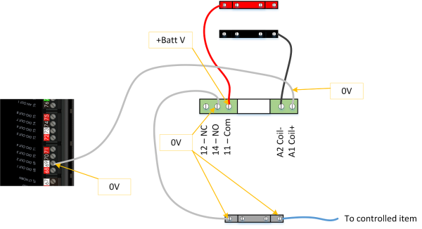
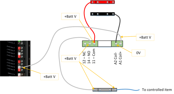
- With an output switched on, the led for that output should be on and the output should measure +BATT DC volts to ground. This should be true whether there is a load connected or not
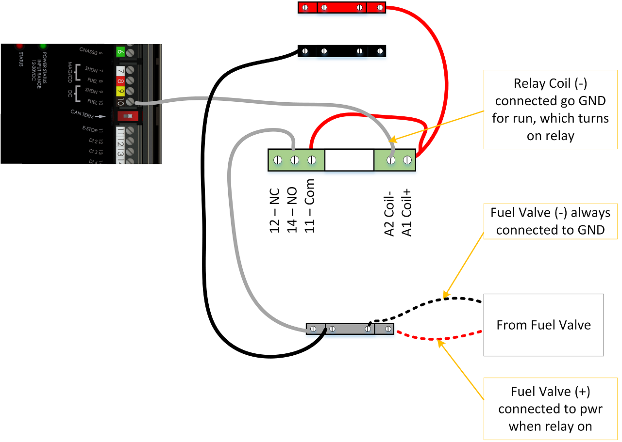
- The following shows the most common output wiring for active high devices (e.g. valves, pumps), and voltages to GND in both the on and off state. Check the panel schematic to verify that this is the relay wiring used. The voltages indicated can be checked in each state to see where the voltage is being lost.
Typical relay wiring showing DO off:
Typical relay wiring showing DO on:
Fuel valve operates incorrectly
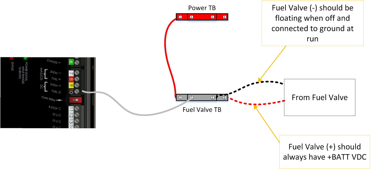
- The fuel valve is typically controlled from annunciator pin 10. This pin is active low (grounded during run). This may be wired directly to the low side of the fuel valve, or may be routed through a relay. Both options are shown in diagrams below. Typically, the direct option is used on smaller HP panels and the extra relay option is used on higher HP panels.
- With engine off, check continuity to ground at pin 10. There should be no continuity to ground.
- If there is continuity with the engine off, remove the phoenix block and check the pin again. If there is still continuity to ground, the board may have an issue.
- If there is no continuity to ground at the board pin, but when the phoenix terminal block is plugged in there is continuity to ground, then there is a short in the panel or relay wiring holding the pin at ground.
- When the fuel valve should be on (when the annunciator is in full run state, e.g. B timers counting down OR in state “Waiting for ECU to start”), check continuity to ground at the pin 10 again. At this point there should be continuity to ground.
- If there is not, there is likely a board issue
- If there is, check the wiring past the pin to see if the relay is coming on. Verify that the expected voltages are present around the fuel valve relay (see drawings below)
Typical fuel valve wiring with FV- running to board (early panels):
Typical fuel valve wiring with FV controlled by external relay:
Control Issues
Startup fails with “ECU fails to start” but the unit did start (CAT engines)
This code means that the annunciator did not detect an RPM above the crank terminate RPM before the startup timer expired.
- Did the Brain home page show RPM when the engine was running?
- NO: Check that the EDT tab shows up on the home page. If not, go to Settings - Engine Data Translator and select mode "ADEM 3/4". If the tab already was present but there was no RPM, check the ECU CAN and ECU CDL connections against the schematic to get the engine data working between the CAT panel and the EMIT panel. See also the information here
- YES: The time that the Brain is waiting for the unit to start may be too short. If needed, adjust the timer at “Brain” -> “Output Setup” -> “ECU Settings” or “System Output Scheme”. By default it is 60 seconds, but it can be increased to give the ECU more time to start up
Startup fails with “ECU fails to start” but the unit never tries to start (CAT engines)
The Brain uses two signals to signal the engine should run, "Driven equipment ready" which is turned on during standby, then "Run/Start" which turns on after pre-lube. For detailed background information see this page.
The below steps assume that the CAT panel / engine never tries to start at all. If the start sequence on the engine begins (e.g. engine pre-lube starts) but doesn't finish starting then the issue is on the engine side and isn't relevant to this section.
- Verify that the engine switch position is in "Auto", if it is an option.
- Is the panel configured for ADEM mode? Go to Settings - Brain - Outputs Setup - ECU Selection and make sure "CAT ADEM" is selected.
- Does the EMIT panel try to start at all? After pre-lube (if used) the panel should go to the state "Waiting for ADEM to start". If it never reaches this state, check the alarm page or the Brain State page (bottom-right of the home screen) to see what is preventing the start sequence from advancing.
- Does the "Driven Equipment Ready" output exist? Go to Settings - Brain - Outputs Setup - Digital Output Function Selection. Usually DO-3 is used.
- YES: Go to (5)
- NO: Check the schematic for the correct output for Driven Equipment Ready. Select that output and pick the row for ADEM DER to assign it to that output. DONE
- Does the "Driven Equipment Ready" relay work? When you press RESET the panel should go to "Standby" and the driven equipment ready relay should come on (Usually CR3). Pressing STOP should cause it to turn back off.
- NO, relay does not toggle: Check with a voltmeter on the Brain output (usually DO-3) if it toggles to about 24V when going between RESET (standby) and STOP. If it doesn't toggle, the module is bad. If it does toggle but the relay doesn't, either the relay is bad or either the A1 or A2 relay wires are mis-routed or bad. Verify the relay wiring against the schematic. DONE
- YES the relay toggles: Go to (6)
- Does the "Driven Equipment Ready" relay output work? If possible, find on the CAT panel where the driven equipment status is shown. This isn't present on all CAT panels. Toggle between RESET and STOP and see if the driven equipment status changes.
- NO the driven equipment status does not toggle on the CAT panel, OR the DER status is not available on CAT panel: Use a voltmeter in resistance mode to check continuity between the schematic TB labeled "DIGITAL RETURN" and the TB labeled "ADEM D.E.R.". This should have continuity after RESET press and lose continuity after STOP press. If it doesn't work as described, the relay is bad or the relay wiring on the output side (pins 11/14) is mis-wired or bad. If it does work, check the wiring from the TBs mentioned to the CAT panel, and verify the wires are landed in the right location in the CAT panel as noted on the schematic. If all the wiring is ok and the resistance test is ok, go to next step if there was no DER status shown. If the DER status was shown the input may be bad on the ECM.
- YES the status toggles: Go to (7)
- Does the "Run / Start" relay work? Go to Settings - Brain - Output Status / Testing - Digital Out testing. Toggle DO-2 on and off and see if CR2 toggles on and off.
- NO: Check with a volt meter if DO-2 on the Brain changes between 0v and 24v referenced to ground while the test page is used to toggle the output. If not, the module is bad. If it does then the wiring to A1 or A2 of the relay CR2 is bad, or the relay itself is bad. DONE
- YES: go to (8)
- If the engine is an ADEM4 with OCP or any ADEM3:
- Check the schematic to see if it shows a jumper required between 113,B and 112,B. If the schematic shows this jumper, make sure it is installed in the panel.
- With a voltmeter in resistance mode, clear the DO test page and press STOP on the panel. Next, check resistance between "DIGITAL RETURN (F)" and "ADEM RUN START (C)" which should show no connection. Then check between "DIGITAL RETURN (F)" and "STOP / START (E)" and it should show continuity. Next, force on DO-2 with the digital out testing. While DO-2 is on from "DIGITAL RETURN (F)" and "ADEM RUN START (C)" should now show continuity and between "DIGITAL RETURN (F)" and "STOP / START (E)" should now show no continuity. If these continuity tests fail, then the relay is bad or one of the three output wires of the relay (11,12,14) are mis-wired or bad. DONE
- If the continuity tests pass, verify the wires from DIGITAL RETURN, ADEM RUN START, and STOP/START (OCP only) are wired correctly from the panel to the CAT panel and landed in the correct CAT terminal blocks according to the schematic.
- For A3 engines, make sure there is a jumper installed between NORMAL STOP and BATTERY RETURN in the CAT panel. This would be from 40-19 on a 3500 and 2-25 on a 3600.
- Check that the CAT setup is correct according to this page.
- If all the above is ok and it still doesn't start the input on the ECM may be bad or there may be an ECM to CAT panel wiring issue preventing the three signals (driven equipment ready, Start, and stop) from reaching the ECM.
- If the engine is an ADEM4 with an HMI:
- With a voltmeter in resistance mode, clear the DO test page and press STOP on the panel. Check resistance between "ADEM RUN START (C)" and "START/STOP IN (X)". It should show no connection. Use the DO test page to force on DO-2. The resistance from C to X should now show continuity. If this test does not pass, the relay is bad or one of the output wires of the relay (11,12,14) are mis-wired or bad. DONE
- If the continuity tests pass, verify that the wires from "ADEM RUN START (C)" and "START/STOP IN (X)" run to the CAT panel properly and land in the correct locations according to the schematic.
- If all the above is ok and it still doesn't start the input on the ECM may be bad or there may be an ECM to CAT panel wiring issue preventing the signals from reaching the ECM. There could also be a wiring or relay issue in the HMI box. With driven equipment clear (CR3 on) the panel simply shorts CAT TB 5 to 51 to start. This could be tested manually, if it fails then the issue is on the engine side.
Engine shuts down on fault normally, but manual stop causes the shutdown to get stuck
- The logic on Digital Input 27 is probably backwards (ADEM Run Status). With the engine fully off, this input needs to be faulted. If it isn’t, try flipping Normally Open / Normally Closed, and then check the input wiring. The input should go from faulted to unfaulted when the engine starts up. The ADEM should be energizing the relay labeled “ADEM RUN SIGNAL” when the engine starts up (see panel schematic for relay numbering).
- The CAT panel could also have a cooldown period enabled. For a normal stop (without a fault) the engine is allowed to cool down and stop when the cooldown period is complete. The cooldown period length is a setting on the CAT panel or through CAT ET.
Engine shuts down on fault “DI-27 ADEM RUN STATUS”, even though the ADEM doesn’t show a fault code
- This could be an issue with the Driven Equipment Ready circuit (usually CR3), Start/Run circuit (usually CR2), or run status circuit back to DI-27
- For each of the above three circuits, make sure all connections are correct and secure. It is also possible the relays are faulty.
Engine or compressor post lube do not work
- If the lube supply gas is past the start gas block valve, then the start gas needs to open on engine shutdown to allow for the post lube. Make sure the annunciator and EIM are up to date, and navigate to “Annunciator Setup” -> “Outputs Setup” -> “Start Gas Valve”, and enter a value for the post-shutoff time to turn on the start gas valve.
Engine will not start, throwing code "DI-27 Not faulted...", CAT engines
Input DI-27 is used to track the run status of the engine. It will be clear (closed to ground) when running. The above code will throw if the input is clear when the unit is off, which should not be possible. See background information here
- Is the input set up? Go to settings - Brain - Input Setup - Digital Inputs - DI-27. It should show up as "ADEM RUN STATUS".
- YES: Go to (2)
- NO: Go to Settings - Brain - Outputs Setup - ECU Selection and select the proper ECU. DONE
- Does the input work? Disconnect the wire going into DI-27 on the Annunciator/Brain. Take a small jumper wire and touch DI-27 to the back panel. The red light next to the pin should turn on/off as the wire is touched to the back panel.
- YES: Reconnect the original wire and go to (3)
- NO: The module input is bad. Replace the module. DONE
- Does the relay work? Find the run signal relay on the schematic. (Usually this is CR-9). With a voltmeter, check that A1+ terminal of the relay shows ~24 volts referenced to a ground.
- YES: Go to (4)
- NO: Check the wiring from A1+ to the terminal block and the same terminal block to the CAT panel. Check the wire where it lands in the CAT panel, verifying against the pin table in the schematic. Use a meter if necessary to measure voltage to see where it is lost. Once voltage is repaired to appear at A1+ again it should work. DONE
- Does the relay toggle? Disconnect A2- on the run signal relay and attach a small jumper wire which can be touched to ground (e.g. the back panel). As the wire is touched to ground the relay should turn on, and the light by DI-27 on the brain should be toggling.
- YES both things happen: Reconnect original A2- wire and go to (5)
- NO: Either the relay is bad, or the output two wires on the relay are faulty. Change the relay and verify the two output wires (on relay terminals 11 and 14) are routed to the proper place and are not loose or have any breaks. DONE
- Is the relay always on (powered)?
- YES: Check the wiring between A2 and the terminal block, and the terminal block to the CAT panel. Verify that the wire is landed on the proper CAT terminal block according to the schematic. If that is all correct the terminal on the CAT ECM may be bad and always grounding the output.
- NO: Go to (6)
- Final checks
- Verify the wiring from A2 to the terminal block, and the terminal block to the CAT panel
- In the CAT panel, try shorting the run signal ground wire to ground and see if the relay toggles. If so, the wiring is ok back to the relay and the CAT ECM output must be bad or wire landed in the wrong location. If it does not toggle, there is some connection issue between that point and the relay.
AFRC 20230 20235 20360
Input Issues
Narrowband O2 reading is 0 or otherwise incorrect
- Note that the O2 reading will not show up until the run signal is met, under AFRC “Setup” -> “Run Signal Trigger”
- If the AFRC is displaying the O2 reading in units of lambda (λ), the sensor type setting is incorrect. Go to the AFRC setup and change the O2 type to Narrowband.
- With the AFRC plug disconnected, the AFRC screen should show an O2 reading of around 450-550 Mv. If not (assuming the run signal is met), the board may be damaged.
- If above passes but goes to zero when the sensor is plugged back in, unplug the harness at the sensor end. Once again the reading should go to 450-550 Mv.
- If not, the harness is grounded out, or the DPV and O2 harnesses are swapped.
- If above passes, check with a multimeter on the loose harness going back to the panel that V DC from pin “B” to any ground is around 0.45-0.55 volts. If it is not, the harness itself is miswired or not landed correctly.
- If above passes but the reading is still zero when plugged in, then the O2 sensor itself is damaged, or the O2 reading is truly very lean
- If the sensor is consistently low (lean), the sensor may be at its lifetime
Wideband sensor incorrect or erratic
- Note that the O2 reading will not show up until the run signal is met, under AFRC “Setup” -> “Run Signal Trigger”
- If the AFRC is displaying the O2 reading in units of mV, the sensor type setting is incorrect. Go to the AFRC setup and change the O2 type to wideband.
- Verify all three shield wires are connected to the ‘drain’ terminal
- If possible, a continuity check can be done from the plug end to the board. The wiring should be:
- Pin 1: White
- Pin 2: Orange or Blue
- Pin 3: Red
- Pin 4: Black
- Pin 5: Green
- Pin 6: Yellow
Thermocouple Reading Incorrect
- If the TC reading is consistently low only with the engine running, the thermocouple may be picking up noise. If available, a .01uF capacitor in the terminal block may fix the reading. If an annunciator is present, the TC can be connected to the annunciator instead and it will be shared with the AFRC if named properly.
- Verify the polarity of the TC wires are correct
Analog input incorrect
- (If the sensor has a plug) Disconnect the plug and check the two pins on the harness going back to the panel with a voltmeter. One of the two should have +12V to a chassis ground. If not, the harness or panel wiring has a break.
- With the sensor re-connected, check the signal pin to ground (e.g. pin 9 to ground). It should read around 0.5 V – 3.3 V.
- If above does NOT pass, try connecting the signal wire to another analog input (e.g. move pin 9 to 12 on AFRCA). If it starts working, there is a problem on the AFRCA board with the original input pin.
- If the other pin does not work either, the cause is likely one of the following:
- There is a break in connection between the module and the end of the harness
- The wires are misconnected or backwards
- The sensor is bad
Output Issues
DPV does not move or may not be moving
- Unplug the DPV at the module and on the unplugged phoenix connector check the resistance from A to D, and the resistance should be roughly 50 ohms. Similarly, the resistance from B to C should be 50 ohms. If not, there is a break in the connection in the harness or at the valve itself. The O2 and DPV harnesses could also be swapped.
- Run the DPV in manual on the EIM open and closed, and see if the O2 reading shifts. If so, the DPV is operating. If closing the valve causes the engine to go rich, then some of the wiring is swapped and the valve is operating backwards.
- If the first step above passes but the DPV is definitely not moving, the board itself may be bad
Control Issues
DPV limit stays at/near maximum, or AFRC throws “loss of control” alarm
- Adjust the fuel pressure to get the valve more in the center of the range
- Verify in manual mode that the DPV is moving in the correct direction
In ‘Autocontrol’ mode, the AFRC tends to rest very rich
- Lower the ‘postcat lean threshold’ 50-100 points
- Adjust rich/lean setting up
Ignition 20270
Input Issues
General Input Checking
On the ICM home page, the ‘Input Information’ box can be selected to view the position input information. While cranking, both the flywheel teeth input and the index input (either another MPU or the hall sensor) should be shown as moving. Also, the “Additional Debug” button can be checked on this page both before and after cranking to see if the “Input Counts” have increased.
RPM Reads "0" when cranking
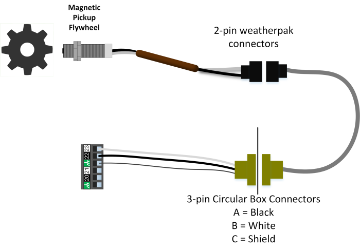
A general diagram of the MPU circuit is shown below
While the flywheel turns, the MPU generates an AC voltage wave where the frequency is equal to the speed of the flywheel movement.
- Verify that the flywheel teeth MPU is plugged into the correct circular connector. The ICM box has two circular connectors for MPU- one for flywheel teeth and one for the index.
- If above is verified correct, unplug the MPU and use a multimeter to measure AC Volts across the two MPU wires while cranking. It should show around 2-10V AC. If less is shown, then one of the following may be the cause:
- The MPU is bad
- The connection to the plug is bad
- The engine is cranking too slowly to generate proper voltage
- A stronger MPU is needed
- The MPU is not close enough to the flywheel (typically should be ¼ to ½ turn out)
- If test above passes, plug the MPU back in and check the AC voltage at the ICM phoenix plug (pins 22/23) with the phoenix plug removed. Again it should be roughly 2-10V AC during cranking. If less is shown, there is a wiring problem in the harness or box preventing the signal from reaching the ICM.
- If test above passes, plug the phoenix plug back into the ICM and measure the AC voltage again while cranking. If it is low in this case, the ICM MPU input may be damaged
- Verify that the flywheel teeth setting is correct
Hall sensor not moving
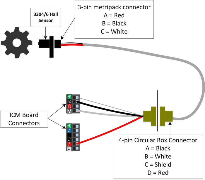
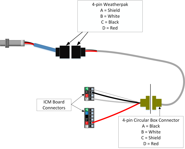
If the input information screen shows the hall sensor not moving, or the alarm “Hall Disconnect” is thrown when using a hall sensor, then the board is not seeing the hall sensor at all. Typical system wiring diagrams are shown below. Verify that pin 14 is used for hall sensor power, and not pin 25.
330x Hall sensor Wiring:
Threaded hall sensor wiring:
- With ICM powered, unplug the hall sensor at the engine (or aux pickup) and verify the following on the harness end:
- 330xB hall sensor:
- Pin A- DC V to ground should be 12 V
- Pin B- Resistance to ground should be < 1 ohm
- Pin C- DC V to ground should be 5 V
- Aux pickup connector
- Pin A- Resistance to ground should be < 1 ohm
- Pin B- DC V to ground should be 5 V
- Pin D- DC V to ground should be 12 V
- Threaded hall sensor with 4-pin weatherpak (checking on weatherpak):
- Pin B- DC V to ground should be 5 V
- Pin C- Resistance to ground should be < 1 ohm
- Pin D- DC V to ground should be 12 V
- 330xB hall sensor:
- If any of the tests in above fail, there is wiring or connection issues in the harness or box.
- If above passes, jump a wire from ground to the pin on the connector that is listed as “DC V to ground should be 5 V” above. For each time grounding that pin, the hall sensor input counts on the input status screen should increase. (Note: The input count dialog aka ‘Additional Debug’ has to be closed and re-opened to update the input counts).
- If this does not work, there is a connection problem between the end of the harness and the ignition board, or a problem with the ICM board itself.
- If above passes, remove the hall sensor and move a magnet to see if the input counts increase. For the aux pickup, plug back in and spin the engine or remove and spin the input shaft manually.
- If this fails, the hall sensor itself may be bad
TDC MPU Index not moving
If using a mag pickup for the TDC index, follow similar troubleshooting steps as Flywheel teeth mpu above, except at the board the wires run into pins 20/21.
Shutdown pin input not working / Ignition is not in "External shutdown" when engine is off
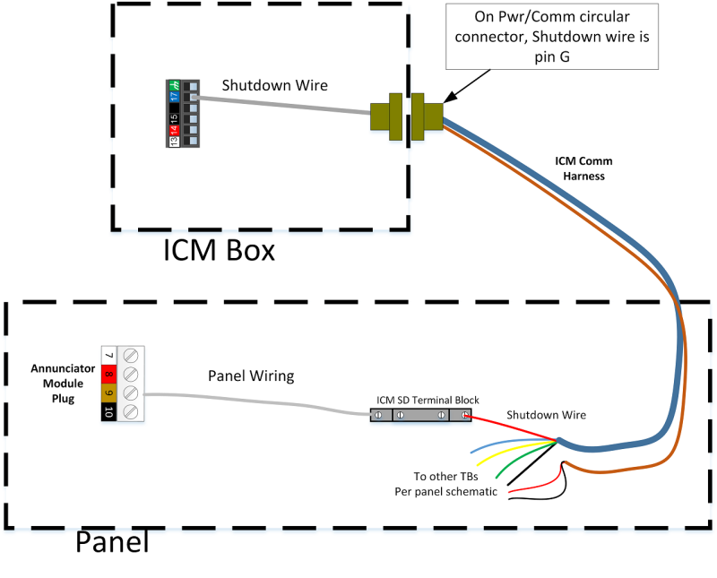
The general wiring of the shutdown circuit is shown below.
- Disconnect the annunciator plug (or disconnect the shutdown wire at the annunciator). Jump the disconnected wire (or Pin 9 on the disconnected phoenix block) to ground. Within a few seconds the ICM status should change to “Externally disabled”.
- If above passes, then the problem is with the annunciator or the wrong annunciator pin is used
- If above fails, unplug the phoenix connector on the ICM board (13-18). Jump pin 17 on the board itself to ground, and see if the status changes to “Externally disabled”.
- If above passes, the problem is with a wiring connection between the ICM board and the annunciator pin. Check each of the connection points in the drawing above.
- If above fails, the problem is in the ICM board itself.
Hall sensor or TDC index moving, but erratic or not resolving correctly
- Verify that the ignition setup is correct. The inputs shown as active in step 1 of ignition setup should be the same as the sensors on the engine.
- Verify that all the connections are well established (see wiring info in “Hall sensor not moving” above)
- Route the hall harness as far away from the coil harness and other noise sources as possible
- If using the flange mounted hall sensor, make sure that the sensor is well seated against the engine.
Output Issues
One or more coils do not fire
- If no coils fire, first verify on the input status screen that the ignition is even trying to fire. If not, troubleshoot the inputs using the above sections
- Make sure the ICM status shows ‘Ready to Start’ before starting the crank
- Using the Ignition “Setup and Testing” -> “Engine Off Diagnostics and Testing” each cylinder can be tested with the engine off. During each test, every coil positive pin should be energized with battery voltage, but only the coil under test will have its negative pin grounded out during fire.
- If the ICM shows the test in progress but there is no voltage at the positive pins, there is a connection issue in the harness or ICM Box
- If the ICM shows the test in progress but the pin is not firing, try a few other coils. The negative wire may be mixed up with another coil.
- Swapping a coil/secondary/plug with a neighboring cylinder may reveal a bad part
Coils fire in test, but when cranking engine one or more do not fire
- Make sure the input status shows that the tooth count is good. If the index input is incorrect some coils may be prevented from firing
- Make sure the dwell time is set long enough to fire the plugs while the cylinders are compressed
- Check to see if any secondary leads appear to be arcing out. The voltage demand in compression will be higher than during engine off testing, and misfires will be more likely.
ICM Module does not appear on EIM/DCT screen
- Verify that the module power light is on, if not check power wiring and fuses
- Check that the CAN termination switches are in the correct direction. Any module with only one can connection (at the end of a chain) should have the switch terminated. Any module in the middle with two connections in the can pins should have the switch unterminated. The ICM will always be at the end of the chain since it is on the skid. The CAN connection is in the power/comm harness (blue/green/yellow wires), and typically runs to terminal blocks that jump to the next module.
- With all modules plugged in and everything powered off, checking the resistance between CANH and CANL of any module should read about 60 ohms. If the ICM is at the end of a chain and it is unplugged, the resistance between the two pins should go to 120 ohms.
- If the above is not true, there is likely a problem with the termination switch positions, or one of the two can wires has a disconnect somewhere
ICM module resets during operation or throws reset code
- Verify that there are good ground connections directly to the skid. If needed, run a chassis wire from the ICM board to the engine block.
- Occasionally the ICM will reset on shutdown when all the coils are shut off, after the engine shuts down for another reason.
- Verify that nothing is loose in the power wiring / fusing
- The board may have a hardware issue that causes resets (contact EMIT)
Control Issues
Spark durations are abnormally low on one or more cylinders
- Spark plug could be fouled or the gap too wide
- The dwell time may not be set high enough for the compression of the engine
- The fuel mixture may be overly lean
Spark durations are abnormally high on one or more cylinders
- The spark plug gap could be too narrow
- The secondary circuit could be grounded out or misfiring. Replace the secondary lead if needed.
- The compression on the cylinder may be low
- The dwell time may be set too high
Ignition displays “Bad Configuration”
- Update to the latest ICM version to make sure any bad config values are cleared out
- Make sure there aren’t two cylinders firing the same pin
Timing light shows a timing that does not match what is displayed on the screen
- Use the Ignition “setup” -> “Timing Calibration” screen to calibrate the timing.
Ignition displays “Bad peak count” fault and/or has erratic timing
- See the debug steps above under “Hall sensor or TDC index moving, but erratic or not resolving correctly”
- If the flywheel has any broken teeth, make sure that the configuration is set to the original number of flywheel teeth
- Make sure the flywheel is relatively clean of debris
Governor / Speed Controller 20310
GOV Input Issues
RPM Reads “0” when cranking
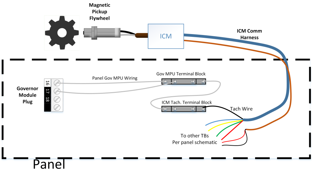
General input wiring is shown below.
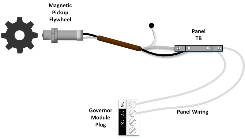 Wiring through panel terminal block
While the flywheel turns, the MPU generates an AC voltage wave where the frequency is equal to the speed of the flywheel movement.
If no ICM is present on the system, OR if an ICM is present but two flywheel teeth MPUs are used:
- Unplug the MPU and use a multimeter to measure AC Volts across the two MPU wires while cranking. It should show around 2-10V AC. If less is shown, then one of the following may be the cause:
- The MPU is bad
- The connection to the plug is bad
- The engine is cranking too slowly to generate proper voltage
- A stronger MPU is needed
- The MPU is not close enough to the flywheel (typically should be ¼ to ½ turn out)
- If test above passes, plug the MPU back in and check the AC voltage at the governor phoenix plug (pins 16/17) with the phoenix plug removed. Again it should be roughly 2-10V AC during cranking. If less is shown, there is a wiring problem in the harness or panel preventing the signal from reaching the governor.
- If test above passes, plug the phoenix plug back into the governor and measure the AC voltage again while cranking. If it is low in this case, the governor MPU input may be damaged.
- If above passes, check these final items:
- Verify the flywheel teeth setting is correct
- Verify there is no alarm for ‘governor sw error’ indicating the test version is installed
- The governor board may be bad
If an ICM is present on the system
Often, the ICM Tachometer output is wired into the governor MPU input as shown. Note that the Tach goes to one of the governor MPU inputs, and the other is not connected (floating).
- Navigate to Ignition ‘Setup and Testing’->’Timing Calibration / Tachometer Output’, and verify that the tachometer pulses per revolution is set to the number of flywheel teeth. Verify also that both the ICM and governor main setups have the flywheel teeth setting correct.
- If above is correct, check where the tach wire lands in the panel (which is the black wire on the ICM comm harness), and check the DC Hz on the tach wire (removed from terminal block) to ground. During crank, it should go from 0Hz to around 500Hz – 2KHz. If it does not:
- Verify that the tach connection in the ICM box is secure
- The ICM box may have a damaged tach circuit
- If above passes, re-connect the tach wire and check the same DC Hz on the MPU+ pin on the governor (16) during crank then the MPU- pin (17) during crank. One of the two should have the 500Hz – 2KHz during crank. If not:
- A connection may be miswired or missing from where the tach lands back to the governor module. A continuity check from the tach terminal block back to pins 16/17 of the governor can help track down a missing connection.
- The governor board MPU input may be damaged
MPU reads more than 0, but is not correct
If the MPU is reading a faulty RPM, verify the following
- Make sure the flywheel teeth setting is correct
- If an ICM is present on the system, verify that at the page Ignition ‘Setup and Testing’->’Timing Calibration / Tachometer Output’, the tachometer output pulses per revolution is set to the number of flywheel teeth
- Verify that all connections are secure at the MPU plug and where wires land in the panel and governor module
- The MPU may not be screwed in far enough. Verify it is within ½ to ¼ turn of the flywheel.
- The MPU harness may be picking up noise. Make sure it is routed away from noise sources, and the drain wire is connected to ground.
The throttle position does not show around 0% position when the engine is off
- The throttle may need to be re-calibrated. Navigate to Governor ‘Setup’ -> ‘Throttle Calibration’ and hit ‘calibrate now’.
- If above does not fix the issue, see if the position appears to change at all while the calibration is taking place, if not, go to ‘Throttle not moving’ below
- If the position is moving but the calibration still does not complete successfully, go to ‘throttle feedback problems’ below
Throttle Feedback Problems
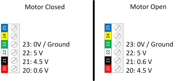
The Bosch throttle bodies use four feedback lines (terminals 20-23 on the governor module). Typical voltages are shown below. The actual feedback voltages (20/21) will vary ~0.3V between motors. The motor can be moved through calibration or manually.
- If voltage does not appear on 22 (5V) but the governor module is powered up, there is likely a problem with the governor board
- If voltage does appear on 22, but does not appear on 21/20, check for a bad connection somewhere between the module and the throttle body
- If voltage appears on only one of 21/20, the other connection has a break between the module and the throttle body
- If the voltages are roughly correct and the motor can move, but the calibration is still failing, it could be because of a problem with the pcb (preventing the reading of the voltage) or a bad throttle body (where the feedback potentiometer is not functioning correctly).
Panel switches reading incorrectly
If the EMIT Brain is not Used
Each of the panel switch inputs (pins 8-14 on the governor module) operate by closing to ground. At any given time one of the inputs Idle/Auto/Manual should be closed to ground, and sometimes one of the Speed+/- may be as well.
If no mode is closed to ground, the governor defaults to ‘idle’, so the idle pin (8) is not connected in panel applications.
- If the module is not reacting properly to the switches, check continuity to ground on each of the input pins as the switch is moved in/out of the position related to that pin label. The pin should be connected to ground (showing <2 ohm) when the switch for that pin is selected
- If this test fails, look for wiring errors or breaks in the switch blocks. Green blocks are normally open and red blocks are normally closed.
- If this test seems to pass but the governor still shows the wrong switch position, the module may be bad. Try unplugging the two phoenix blocks for the switches and jumping pin 11 (ground) to one of the mode selects to see if they change the mode.
If the EMIT Brain is Used
The panel switches will wire to the brain and it will send the positions to the speed module. See the troubleshooting section for Brain - Switch issues.
GOV Pressure Sensor(s) not reading any value
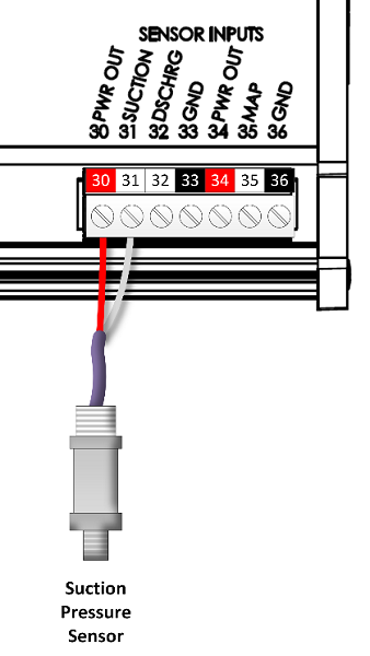
Typical sensor wiring is shown below for one sensor. If an annunciator/Brain is present, the sensor will likely not be wired to the governor and this section can be skipped.
For an EMIT harness, the colors will be as shown above with red on a PWR OUT and the white wire into the required input. If a bare sensor without a plug is wired in, a black wire will be used for the signal wire instead of white. From the governor home page, the ‘Sensors’ button will show the raw and scaled value for each analog input.
- (If the sensor has a plug) Disconnect the plug and check the two pins on the harness going back to the panel with a voltmeter. One of the two should have +12V to a chassis ground. If not, the harness or panel wiring has a break.
- With the sensor re-connected, check the signal pin to ground (e.g. pin 31 to ground). It should read around 0.5 V – 3.3 V.
- If above does NOT pass, try connecting the signal wire to another analog input (e.g. move pin31 to 32). If it starts working, there is a problem on the governor board with the original input pin.
- If the other pin does not work either, the cause is likely one of the following:
- There is a break in connection between the module and the end of the harness
- The wires are misconnected or backwards
- The sensor is bad
Pressure sensor reads a value, but it is not correct
If the pressure sensor is reading an incorrect value, it is most likely caused by the scaling not being set correctly. This can be adjusted in Governor “Setup” -> “Sensor Setup”.
If the annunciator is connected to the normal pressure sensors, it should be sharing the suction and final discharge stage values to the governor. If it does not:
- Make sure the built-in names for the stages are used on the annunciator so that the system knows how to sort out the input. E.g. choose ‘Suction’ for first stage suction instead of using a custom name like ‘First stage suction’.
- Make sure the module firmwares are relatively up to date.
Output Issues
Governor does not show up on EIM or DCT
- Verify that the governor is powered up and running. The Power status LED should be green, and the STATUS led should be pulsing green every second or so.
- If not, check power wiring. If the STATUS led is not pulsing and the module is not showing up on the EIM/DCT, the board could be non-functional because of electrical damage.
- Check that the CAN termination switches are in the correct direction. Any module with only one can connection (at the end of a chain) should have the switch terminated. Any module in the middle with two connections in the can pins should have the switch unterminated.
- With all modules plugged in and everything powered off, checking the resistance between CANH and CANL of any module should read about 60 ohms. If the governor is at the end of a chain and it is unplugged, the resistance between the two pins should go to 120 ohms.
- If the above is not true, there is likely a problem with the termination switch positions, or one of the two can wires has a disconnect somewhere
Throttle not Moving
- Unplug the throttle body connector at the governor module (phoenix block with numbers 20-25). Check the voltage between pins 24 and 25 (MOTOR-, MOTOR+) on the module. When someone hits ‘Calibrate Now’ on the governor calibration screen, for a couple seconds there should be around 12V between the two pins. If not, the board likely has an issue.
- If above passes, check the resistance between on the unplugged phoenix connector between pins 24 and 25. The resistance should show around 1-5 ohms.
- If it does not, there is a connection issue between the throttle body and the module. Verify wiring from the phoenix connector to any terminal blocks, and from there to the end of the harness. Verify that the harness is plugged in.
- If showing around 1-3 kohms, it is possible that some of the wires are swapped or harness mixed up.
Control Issues
RPM is erratic
- Navigate to governor “Setup” -> “Engineering Setup”. Try adjusting the “Throttle gain setting” up and down (especially up). If this does not have an effect, return to “50”. Similarly try increasing or decreasing the “RPM gain adjustment”. In general, increasing the RPM gains will cause faster response but potentially lower overshoot. Lowering the RPM gains leads to slower response but less overshoot.
- Verify that fuel pressure and AFR are relatively steady
- Make sure there is not an active alarm for throttle feedback error. If there is, recalibrate the throttle with the engine off.
- If the throttle body has been in use for a long time, the gear may have enough wear in it that the throttle plate has too much slack
Engine will not start
- While cranking, verify that RPM is showing up. If it is not, go to section above “RPM Reads ‘0’ when cranking”
- If above is ok, verify that the throttle goes to an open position during cranking. If not, go to “Throttle not moving” above.
- If above is ok, the starting throttle may need to be adjusted. This is under governor “Setup” -> “Engineering Setup”.
EIM 20200
Screen boots to the EMIT logo, but is stuck there
- Usually this is an issue with the internal memory and must be repaired by EMIT
- The SLC-SD card lock may be grounded against the case
- The SLC-SD card itself may have an issue
Screen boots past the EMIT logo, but the application does not start
- Usually this will require repair
- An SLC-SD card from a different EIM was used and the encryption does not match (Cards cannot be swapped between EIMS)
- The SLC-SD card may be bad
Screen is always black
- Try cycling power on the screen
- Verify that the input voltage is between 12 and 30 VDC
- If input power is good but the green power LED does not come on, the EIM needs repair
- Behind back cover, verify that the backlight connection is in all the way
- If all of the above is ok and there is still no boot, the EIM needs repair. It is most likely an issue with the SLC-SD card.
Touch screen input does not detect press in correct location
- The touchscreen may need to be re-calibrated under “System Settings” -> “About” -> “Calibrate Touch Screen”
- If debris accumulates under the bezel it can screw up touch detection. Cleaning around the bezel can fix this issue.
- Sometimes the screen bracket is too tight causing this issue. Remove the back cover and loosen the left and right screen screws slightly (3 per side that go into bezel)
