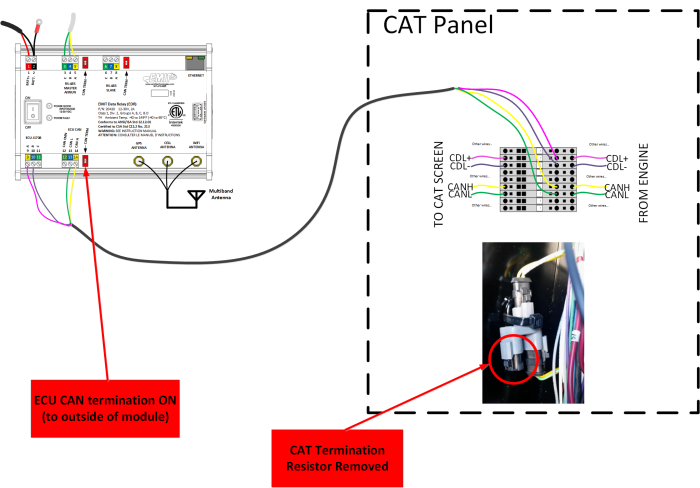
CAN Terminations With CAT Panel
Any CAN bus will need a resistor termination on the two ends. The bus might daisy-chained to many places but there should be exactly two termination at the ends.
On a stock CAT engine there will be a termination plug by the ECU on the engine and another inside the panel box. (Note: Some engines have two busses so there are another two terminations somewhere).
When the EDR, EDT, or DCT is added and connected to the CAN bus then the EMIT module becomes the end of the bus so the resistor plug in the CAT panel is removed.
In the above example, the red switch on the EDR is turned ON (toward the outside of the module) and the CAT resistor plug is removed. This makes the EDR module the new end of the bus and the other end is still at the engine ECU.
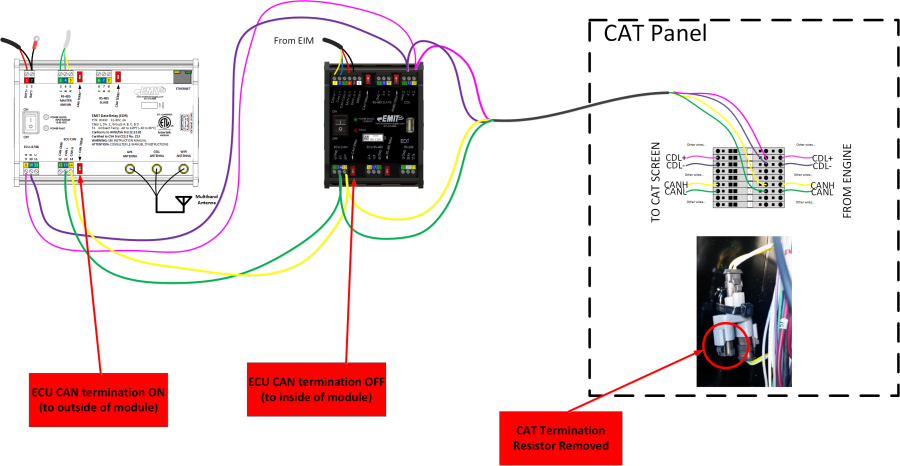
If an EDR is added to an EIM panel then it will have the engine busses daisy chained from the EDT to the EDR. In this case the EDR becomes the new end of the bus and the EDT termination is turned OFF (toward the center of the module).
In the above case there is still one termination on the engine ECU (not shown) and exactly one in the panel box: at the EDR.

