Digital Inputs Detect Loop
Overview
The digital inputs to the Brain are most commonly connected to switches that either close or open on fault. Of the two options, normally-closed setup (where closed to ground is clear and open is faulted) is more safe because a wire breakage will show as faulted.
However, there can also be cases where a wire is somewhere shorted to ground on the skid and the input will always read grounded even when the switch opens. To help avoid this scenario, some versions of the Brain hardware support a "Detect loop" where the input can operate like a normally closed loop while also adding a detection of shorts to ground.
Hardware that supports this feature
Brain s/n 1260-3419 Brain s/n 3690+
Using the Short Detect Mode
Configuration
For any digital input there is an option for "Detect Loop" instead of normally open or normally closed. This option can be selected to turn on the detect loop on that digital input.
Example setup
Wiring
Digital inputs that are using the detect loop are wired differently than normal digital inputs.
Standard Normally Closed Switch
- Contact A : Wires back to the digital input
- Contact B : Wires back to ground in the panel
Detect Loop Normally Closed Switch
- Contact A : Wires back to the digital input
- Contact B : Wires back to AI-10, AI-11, or AI-12 depending on the input number
For digital inputs 1-10, the second leg will go back to AI-10. For 11-20 it will go back to AI-11, and for 21-30 it will go back to AI-12. The digital input setup page will show which AI is used for the 2nd leg.
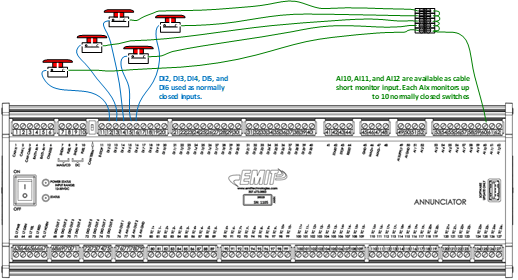
Example wiring for 5 inputs
Not all digital inputs in a section have to be using the detect loop, and only the ones using the detect loop have to wire back to the analog input. For example, if DI-2 to DI-6 have the detect loop turned on then all 5 inputs will have the second leg tied together in the panel then run to AI-10. Separately DI-7 might still use a standard "Normally Closed" or "Normally Open" setup and can tie back to ground for the second leg.
Status and Alarms
When turning on detect loop for a digital input, the system will automatically turn on the required analog input for the second leg. Optionally the gauge for this input can be turned on for status. It will be scaled so that it will show the number of loops detected. For example if 5 switches are closed to the feedback then the gauge will show "5".
If there is no ground short, the digital inputs will operate the same as in a standard mode. Opening the switch will cause a normal alarm on that input, e.g. "DI-2 SCRUBBER 1 LVL". The input fault status will also be shown normally for switch testing.
If there is a ground short detected, then a special alarm will be generated called a digital input feedback fault. This will signify that one of the inputs on that block (e.g. DI-1 to DI-10) is shorted to ground somewhere.

