|
|
| (11 intermediate revisions by 2 users not shown) |
| Line 17: |
Line 17: |
| [[Ignition Alarms]] | | [[Ignition Alarms]] |
|
| |
|
| [[Ignition ICM2 Encoder Visualization]] | | [[Ignition Calibration]] |
|
| |
|
| [[Ignition Wiring Diagram]] | | [[Ignition Wiring Diagram]] |
|
| |
|
| [[Ignition Singly Cylinder Dropout Test]] | | [[Ignition Single Cylinder Dropout Test]] |
| | |
| | [[Spare_Parts_Reference#Ignition|Ignition Parts]] |
| | |
| | [[330xA Timing Disc Installation]] |
| | |
| | [[Ignition External Timing Adjustment]] |
|
| |
|
| == Overview == | | == Overview == |
| Ignition overview: https://www.youtube.com/watch?v=H8GPSxc_so0 | | Ignition overview: https://www.youtube.com/watch?v=H8GPSxc_so0 |
|
| |
|
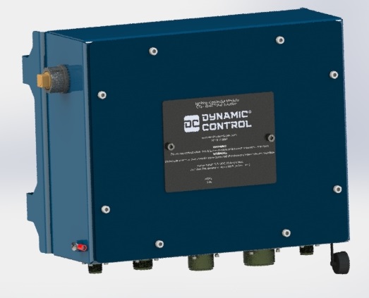
| The EMIT Ignition Controller Module (ICM) is an electronically controlled ignition system that features highly accurate and reliable spark control and monitoring capabilities through the use of transistorized inductive technology. The ICM is available in two types: The ICM1 and ICM2, both of which are available in versions with a maximum of 8 or 16 cylinders. The ICM2 is connected directly to the auxiliary drive of an engine for sensing the position of the engine, while the ICM1 uses external timing sources for applications without an auxiliary drive. All ignition modules offer the same feature set and are appropriate for rich-burn or lean-burn combustion and naturally-aspirated or turbo-charged engines fueled by natural gas or propane. | | [[File:20270-ICM ISO4.jpg]] |
| | |
| | The EMIT Ignition Controller Module (ICM) is an electronically controlled ignition system that features highly accurate and reliable spark control and monitoring capabilities through the use of transistorized inductive technology. The module is available in versions with a maximum of 8 or 16 cylinders. The ignition module is appropriate for rich-burn or lean-burn combustion and naturally-aspirated or turbo-charged engines fueled by natural gas or propane. |
|
| |
|
| The ICM utilizes transistorized inductive technology to build and transfer energy for spark initialization and control. By using the latest transistor technology, a high speed digital signal processor, and high-energy coils for inductive ignition, the ICM achieves precise and accurate control of a long duration spark that burns beyond that of a capacitive discharge system. The longer spark duration provides reliable combustion of the air/fuel mixture and performs particularly well for poorly mixed air/fuel mixtures, poor quality fuels, and lean air/fuel mixtures. Other benefits of inductive discharge systems include superior misfire performance, higher energy transfer efficiency to the spark, and reduced electromagnetic interference. | | The ICM utilizes transistorized inductive technology to build and transfer energy for spark initialization and control. By using the latest transistor technology, a high speed digital signal processor, and high-energy coils for inductive ignition, the ICM achieves precise and accurate control of a long duration spark that burns beyond that of a capacitive discharge system. The longer spark duration provides reliable combustion of the air/fuel mixture and performs particularly well for poorly mixed air/fuel mixtures, poor quality fuels, and lean air/fuel mixtures. Other benefits of inductive discharge systems include superior misfire performance, higher energy transfer efficiency to the spark, and reduced electromagnetic interference. |
| Line 32: |
Line 40: |
| Capacitive discharge ignition systems have a higher peak spark voltage, but due to the corresponding short spark duration does not definitely translate to improved combustion. To overcome this, some capacitive systems need to spark multiple times to ensure the mixture is combusted if the original sparks did not ignite or only partially ignited the mixture. Multiple sparks reduce the ability to control peak cylinder pressure and unnecessarily wear coils, wires, and spark plugs. With the longer spark duration of the ICM, one spark provides sufficient energy to ignite the mixture. | | Capacitive discharge ignition systems have a higher peak spark voltage, but due to the corresponding short spark duration does not definitely translate to improved combustion. To overcome this, some capacitive systems need to spark multiple times to ensure the mixture is combusted if the original sparks did not ignite or only partially ignited the mixture. Multiple sparks reduce the ability to control peak cylinder pressure and unnecessarily wear coils, wires, and spark plugs. With the longer spark duration of the ICM, one spark provides sufficient energy to ignite the mixture. |
|
| |
|
| For an ICM1, the timing input can be sourced from different locations on the engine depending on the application. In wasted spark mode, the ignition utilizes two magnetic pickups: one for flywheel teeth and one for flywheel index to indicate top dead center of the reference cylinder. By using only two magnetic pickups, no additional sensors are needed for the camshaft timing, which is generally more difficult to access for installation. Alternatively, the ignition can use one magnetic pickup on the flywheel teeth and one hall sensor on the TDC of the camshaft to fire only on compression stroke. Lastly, the ICM1 can have the timing source from a camshaft timing disk, which has a timing mark for each cylinder, and an additional mark for the cylinder that is the reference cylinder. | | For an ICM, the timing input can be sourced from different locations on the engine depending on the application. In wasted spark mode, the ignition utilizes two magnetic pickups: one for flywheel teeth and one for flywheel index to indicate top dead center of the reference cylinder. By using only two magnetic pickups, no additional sensors are needed for the camshaft timing, which is generally more difficult to access for installation. Alternatively, the ignition can use one magnetic pickup on the flywheel teeth and one hall sensor on the TDC of the camshaft to fire only on compression stroke. Lastly, the ICM can have the timing source from a camshaft timing disk, which has a timing mark for each cylinder, and an additional mark for the cylinder that is the reference cylinder. |
| | | Configuration, ignition status, timing adjustment, and diagnostic tools are all presented through the EIM or DCT touchscreen display. The touchscreen allows the ICM to be fully accessible and utilized without the need for a PC connection, external software, or any chips or keys. If installed with other EMIT modules, the systems can all be accessed through the same display and user interface. |
| For an ICM2, no external timing inputs are required. The ICM2 bolts directly to the engine’s auxilary drive location (magneto drive) and uses an internal encoder to detect the position of the camshaft. Internal gearing, in a ratio specific to the engine application, reduces the auxiliary drive to the speed of the camshaft.
| |
| | |
| Configuration, ignition status, timing adjustment, and diagnostic tools are all presented through the EIM’s 8” touchscreen display. The touchscreen allows the ICM to be fully accessible and utilized without the need for a PC connection, external software, or any chips or keys. If installed with an EMIT AFRC or EMD, the systems can all be accessed through the same display and user interface. | |
|
| |
|
| Timing control is designed to automatically advance and retard based on changes to RPM and, optionally, load while also being quickly adjusted manually. Accuracy of the timing is based on engine RPM and is reduced as RPM increases. As an example, timing is accurate within +/-0.090 degrees at 1500 RPM and +/-0.180 degrees at the maximum RPM of 3000. Timing ignition adjustment limited to a range of 5 degrees BTDC and 60 degrees BTDC. | | Timing control is designed to automatically advance and retard based on changes to RPM and, optionally, load while also being quickly adjusted manually. Accuracy of the timing is based on engine RPM and is reduced as RPM increases. As an example, timing is accurate within +/-0.090 degrees at 1500 RPM and +/-0.180 degrees at the maximum RPM of 3000. Timing ignition adjustment limited to a range of 5 degrees BTDC and 60 degrees BTDC. |
|
| |
|
| Diagnostic, testing, and control features for the ICM include a range of tools. Conditions for up to eight cylinders at a time can be displayed simultaneously for visual comparison. Various aspects of spark conditions can be setup to provide warnings for potential issues. For engine protection, the ICM offers overspeed and underspeed shutdowns. The ICM can also trigger a warning or shutdown for poor spark performance, such as short spark duration or high misfire count. Other features include verification of timing inputs, verification of coil and harness wiring, top dead center input calibration, compression testing mode, adjustable fuel relay control, adjustable ignition start control, adjustable dwell time, and secondary spark waveform graphing. | | Diagnostic, testing, and control features for the ICM include a range of tools. Conditions for up to eight cylinders at a time can be displayed simultaneously for visual comparison. Various aspects of spark conditions can be setup to provide warnings for potential issues. For engine protection, the ICM offers overspeed and underspeed shutdowns. The ICM can also trigger a warning or shutdown for poor spark performance, such as short spark duration or high misfire count. Other features include verification of timing inputs, verification of coil and harness wiring, top dead center input calibration, compression testing mode, adjustable fuel relay control, adjustable ignition start control, adjustable dwell time, and secondary spark waveform graphing. |
|
| |
| == Testing Tools ==
| |
| The testing tools described in this section are available from the Setup and Testing screen (Pg. 401). Security access of Setup or Engineering is required.
| |
|
| |
| === ENGINE RUNNING DIAGNOSTICS AND TESTING- ICM1 ===
| |
| The Engine Running Diagnostics and Testing screen (Pg. 420) is used to view the current timing source configuration and identify if there are any issues present.
| |
|
| |
| * “Inputs” – Displays the status of the configured input signals
| |
| * “Teeth” – Displays status of the flywheel teeth
| |
| * “Input Noise” – Displays the percentage of erroneous signals detected over the previous 10 seconds
| |
| * “Other Errors / Warnings” – Displays various issues detected
| |
| * “Min Flywheel rotations not yet reached” – The engine has not turned enough times yet to start sparking. User-settable in the engineering screen.
| |
| * “Engine overspeed shutdown” – The overspeed shutdown fault occurred and has not yet been cleared
| |
| * “Engine underspeed shutdown” – The underspeed shutdown fault occurred and has not yet been cleared
| |
| * “Bad configuration- check setup” – The configuration is invalid (e.g. a cylinder is used in the firing order twice)
| |
| * “Critical timing error shutdown” – The TDC signal was lost for 2 seconds while the flywheel was still running.
| |
| * “Hall signal weak” – The hall pulse has been intermittent but occurring at the correct location after missing one or more cam turns.
| |
| * “Previous Shutdown Cause” – Displays the reason for the previous ignition shutdown
| |
| * "None/Reset (Engine has not gone from running to stopped since power on)" – The engine has not shutdown since the ignition has been powered on
| |
| * "Generic stall (ignition was firing when engine died)" – Engine stalled while the ignition was firing
| |
| * "User disabled" – The ignition was killed by selecting the “Shutdown Engine” button from the “System Menu” screen
| |
| * "External disable (shutdown line was pulled low)" – Ignition is disabled from the annunciator
| |
| * "Critical alarm shutdown (e.g. overspeed/underspeed)" – An overspeed or underspeed event occurred
| |
| * "Critical timing fault- timing signals were too poor to continue firing" – The magnetic pickup or Hall sensor signal lost integrity
| |
| * "Generic stall low RPM (ignition was firing when engine died)" - Engine stalled while the ignition was firing
| |
|
| |
| === ENGINE RUNNING DIAGNOSTICS AND TESTING- ICM2 ===
| |
| The ICM2 Engine Running Diagnostics and Testing screen (Pg. 422) is used to view the current timing source configuration and identify if there are any issues present.
| |
|
| |
| * “Encoder” shows encoder status
| |
| * “Counts per rev.” is a factory setting for the encoder
| |
| * “Last rollover” shows what the last rollover for the encoder was, which should always match “Counts per rev”. If this number is slightly off, there could be an encoder or noise issue. If this number is above 60,000, then the encoder is running backwards, in which case the calibration step needs to be completed.
| |
| * “Encoder Turning” / “Encoder Index Moving”: These show the movement of the encoder, which should be “No” when the engine is off and “Yes” when the engine is moving. If these stay “No” with the engine cranking, then there could be an issue with the encoder, drive shaft, coupling (“biscuit”), or internal gearing slipping.
| |
| * “Sparks” shows the total number of sparks since power on, and total number of misfires.
| |
| * “Other errors and warnings” will show other faults, if present. This list is the same as in the ICM1 in the previous section.
| |
| * “Previous shutdown cause” shows the last reason the ignition stopped firing. The list is the same as in the ICM1 in the previous section.
| |
|
| |
| === ENGINE OFF DIAGNOSTICS AND TESTING ===
| |
| The Engine Off Diagnostics and Testing screen (Pg. 421) is used to test ignition component operation and wiring when the engine is off. In this mode you can enter Compression Testing Mode, and can run wiring and firing order tests.
| |
|
| |
| The left box can be used to select an individual cylinder to test sparking to verify wiring. To test a cylinder, select ‘Test’ next to that cylinder. When testing is active, the ignition coil under test will fire continuously. To check the component health or activity, use a spark checker tool or observe the spark information on the right side of the screen. To end the test, select the “End Test” button.
| |
|
| |
| The text labels for the cylinders will illuminate blue while under test. On the Ignition Home screen (Pg. 400), the status will display “Firing Order Test Mode”.
| |
|
| |
| The ‘Compression Testing Mode’ button can be selected when there are no individual cylinder tests taking place. This locks out the ignition system so that the user can crank the engine for a compression test without the coils firing. Click ‘End Test’ to exit this mode.
| |
|
| |
| <nowiki>*</nowiki>Insert Image*
| |
|
| |
| ''Engine Off Diagnostics and Testing Screen''
| |
|
| |
| === TIMING CALIBRATION AND TACHOMETER OUTPUT ===
| |
| The Timing Calibration and Tachometer Output screen (Pg. 423) is used to adjust the ignition calibration value and the tachometer output.
| |
|
| |
| === TDC Calibration ===
| |
| “TDC Calibration” is used to adjust timing to match the actual timing observed through a timing light, if different. Timing disparity between the displayed timing of the ICM and a timing light are due to TDC index trigger bolt being installed not precisely at TDC. Note that the ‘Current Timing Displayed’ value will not change as the offset is adjusted, instead the value read on the timing light will change. Once the timing light matches the current timing, the signal is calibrated.
| |
|
| |
| When doing an initial calibration of the engine, it can be useful to set RPM advance to be constant so that the timing does not move around while calibrating
| |
|
| |
| If the trigger was installed BTDC, the offset will be negative. If the trigger was installed ATDC, the offset will be positive.
| |
|
| |
| === Tachometer Output ===
| |
| The “Tachometer Output” setting is used to set the number of pulses per revolution for the Tachometer Output pin on the ICM. This can be used to display RPMs on other devices, such as a Murphy TTD panel. Press the button to change the number of pulses on the tach output for every flywheel revolution.
| |
|
| |
| If connecting the tachometer output to the MPU input of a TTD panel, the TTD must be configured to match the pulses per revolution set on this screen. The TTD only looks for RPM on the MPU input if the pulses are greater than 17. A value of 100, or more, is recommended.
| |
|
| |
| == Engineering Adjustments ==
| |
| The Engineering Setup screen (Pg. 408) allows adjustments to dwell time, coil startup time, fuel startup time, elevation, and specific gravity.
| |
|
| |
| <nowiki>*</nowiki>Insert Image*
| |
|
| |
| ''Ignition Engineering Adjustments Screen''
| |
|
| |
| === DWELL TIME ADJUSTMENT ===
| |
| Dwell time is the period of time the ignition coil is charged prior to firing the spark.
| |
|
| |
| Dwell times have a direct effect on spark energy and component life. Longer dwell times can provide additional energy to the spark resulting in hotter and longer spark. If the dwell time is excessive, the ignition coil and the spark plug will have a significantly reduced life span. Low dwell times will extend component life but will result in a lower-energy spark.
| |
|
| |
| Primary current and spark durations should be monitored when adjusting dwell time. It is recommended that dwell time does not exceed 2.5ms for a 24V battery system and 6.0ms for a 12V battery system.
| |
|
| |
| Turbo-charged engines and engines with poor quality fuels may require higher dwell times.
| |
|
| |
| Due to dwell time being adjustable, ignition coils damaged due to excessive dwell times are not warrantied.
| |
|
| |
| === IGNITION START ADJUSTMENT ===
| |
| The ignition start adjustment setting sets the number of crank revolutions before enabling the ignition. Additional crank revolutions may be necessary to purge the cylinders of fuel when running in wasted spark mode. On slow-cranking engines it may be desirable to increase this value a few turns so that the ignition timing is more accurately resolved by the time the coils are enabled.
| |
|
| |
| By default, the ignition is configured to start sparking after two flywheel rotations.
| |
|
| |
| === FUEL RELAY ADJUSTMENT- ICM1 ONLY ===
| |
| The fuel relay adjustment setting sets the number of crank revolutions before toggling the fuel relay. This setting can be used to turn on fuel before or after ignition coils have been started.
| |
|
| |
| Generally the fuel solenoid should be started later than the coils so that the cylinders are not overly saturated with fuel when the first sparks occur
| |
|
| |
| A fuel solenoid is optional but recommended if starting in wasted spark.
| |
|
| |
| By default, the fuel relay is configured to engage after two flywheel rotations.
| |
|
| |
| The fuel relay can also be used as a run status if desired, it will always be on while the ignition is firing.
| |
|
| |
| === UNIT ELEVATION AND FUEL SPECIFIC GRAVITY ===
| |
| If using a prebuilt timing map, the unit elevation and fuel specific gravity can be entered, if known, to adjust the timing map for those conditions.
| |
|
| |
| If using a custom RPM/Load advance, the elevation and specific gravity setting will have no effect.
| |
|
| |
| == Alarms ==
| |
| The ICM presents ignition diagnostics in the form of visual tools, user-defined alarms and warnings, and a quick-view for active faults.
| |
|
| |
| === ALARMS AND WARNINGS ===
| |
| Adjustable alarms and faults are available on the Ignition Alarms screen (Pg. 407). Alarm thresholds on this screen can be configured at any time to trigger fault conditions for the events listed below.
| |
|
| |
| <nowiki>*</nowiki>Insert Image*
| |
|
| |
| ''Ignition Alarms Screen''
| |
|
| |
| When an alarm occurs, the “Alarms” button in the footer of the display will flash the “Alarm” text and display the current number of alarms. To clear the alarm, the “Reset Alarm” button must be selected from the Alarm View screen (Pg. 41). The overspeed, underspeed, and critical timing error alarms will shut down the engine. The other diagnostic trigger values will cause an alarm but the engine will stay running.
| |
|
| |
| To set a disable a diagnostic trigger, select the relevant button and press “Disable Highlighted Alarm”. A disabled alarm will show “---“ in its value box. Note that “Overspeed RPM” cannot be disabled.
| |
|
| |
| === RPM Overspeed ===
| |
|
| |
| * “RPM Overspeed” is the setpoint value for a high RPM shutdown
| |
| * This value is configured during the ignition setup process but can be updated at any moment
| |
| * The maximum RPM overspeed setpoint is 3000 RPM
| |
|
| |
| === RPM Underspeed ===
| |
|
| |
| * “RPM Underspeed” is the setpoint value for a low RPM shutdown
| |
| * Alarm is only engaged after a startup grace period expires
| |
| * Startup grace period is adjustable up to 20 minutes
| |
|
| |
| === Spark Duration ===
| |
|
| |
| * A spark duration warning can be configured by defining the “Maximum Spark Duration” and “Minimum Spark Duration” values
| |
| * Valid ranges for spark duration are between 0.5 and 20 ms
| |
| * A spark duration fault provides a warning and does not shutdown the ignition
| |
|
| |
| === Spark Deviation from Engine Average ===
| |
|
| |
| * The spark deviation warning is intended to identify any cylinder or ignition component issues by comparing the individual spark duration with the engine average duration
| |
| * Valid ranges for spark duration deviation are between 0.1 and 10 ms
| |
| * A spark deviation fault provides a warning and does not shutdown the ignition
| |
|
| |
| === Maximum Cycle-to-Cycle Variation ===
| |
|
| |
| * The cycle-to-cycle variation warning is intended to identify any cylinder or ignition component issues by identifying cylinders that exceed a user-define cycle-to-cycle spark duration threshold
| |
| * Valid ranges for cycle-to-cycle variation are between 0.1 and 10 ms
| |
| * A cycle-to-cycle variation fault provides a warning and does not shutdown the ignition
| |
|
| |
| === Maximum Cylinder Misfires ===
| |
|
| |
| * If a cylinder’s spark plug is detected to have not sparked properly a misfire count for that cylinder will be incremented
| |
| * The Maximum Cylinder Misfires value gives a threshold value past which an alarm will be triggered
| |
| * The misfire alarm will show a list of cylinders that are over the threshold value
| |
|
| |
| === (Built In) Critical Timing Error – Missing Index ===
| |
|
| |
| * If the crank TDC index signal has not been detect for 2.0 seconds while the engine is running, the ignition will shutdown and display the fault in the Alarms screen (Pg. 40)
| |
| * Potential causes of this fault include:
| |
| * TDC magnetic pickup installed too far from the trigger bolt to detect
| |
| * Excessive oil and metal shavings on the pole of the TDC magnetic pickup
| |
| * Improper wiring of the TDC magnetic pickup
| |
| * This error will also show similarly in modes that use a camshaft sensor as a TDC reference if that signal is lost for 2.0 seconds
| |
|
| |
| === (Built In) Shutdown Alarms ===
| |
| The Ignition has a variety of shutdown diagnostic alarms that are always enabled. After a shutdown, the EIM will evaluate the conditions of the ignition before and after the engine stopping. If an unusual or problematic condition exists, it will trigger an alarm under code ICM007, and will provide additional information to the user as to what might have contributed to the shutdown.
| |
|
| |
| == ICM2 Encoder Visualization ==
| |
| For the ICM2, the encoder visualization screen can be accessed by going to “Setup and Testing” from the Ignition Home screen, then clicking “Encoder Position / Cam Information”.
| |
|
| |
| This page shows the position of the encoder (camshaft position) and the saved zero point. It can be used to see if the reference cylinder is on the compression or exhaust stroke, and also can be used to see if the calibration was successful (if the red lines are aligned then the flywheel position should be at or near TDC).
| |
|
| |
| If the ICM2 has to be removed for maintenance, this screen should be used beforehand to set the engine at TDC of the compression stroke of the reference cylinder.
| |
|
| |
| <nowiki>*</nowiki>Insert Image*
| |
|
| |
| == Wiring Diagram ==
| |
| <nowiki>*</nowiki>Insert Image*
| |
|
| |
| <nowiki>*</nowiki>Insert Image*
| |
|
| |
| == Single Cylinder Dropout Test ==
| |
| The ignition has the ability to run briefly without firing a single cylinder. This can be used to verify that each cylinder is supplying a similar amount of power to the engine.
| |
|
| |
| WARNING:
| |
|
| |
| Running without firing one cylinder sends unburnt fuel to the catalyst, which is hard on the element. Cylinder dropout tests should only be run briefly, with plenty of time between tests running normally to make sure unburnt fuel is purged out of the system. The test should be used with a moderate load, if the load is too high the engine will probably stall.
| |
|
| |
| The single cylinder dropout test screen is found by navigating from the ignition home page to "Setup and Testing", "Testing Pages" category, then "Single Cyl Dropout Test". To use this test, an EIM version of 2.00 or higher and an ignition version of 1712 or higher are required.
| |
|
| |
| <nowiki>*</nowiki>Insert Image*
| |
|
| |
| ''Single Cyl Dropout Test Screen (Shown during test)''
| |
|
| |
| === Manual Test ===
| |
| Once the engine is running, a manual test can be used by clicking 'Manual Drop One Cylinder'. A dialog will be shown to choose a cylinder, after which the engine will run without firing that cylinder for about 5 seconds. After the test the average RPM and manifold pressure during the test will be shown.
| |
|
| |
| During the test, selecting 'Stop Test' will abort the test.
| |
|
| |
| === Auto Test ===
| |
| If an EMIT governor is present on the engine, the 'Auto' test can be used. The ignition will perform the following sequence during this test:
| |
|
| |
| # The governor will be commanded to hold a fixed throttle position, followed by a short delay
| |
| # Each cylinder will be dropped out for about 4 seconds each
| |
| # At the end of the test, the governor and ignition will return to normal operation
| |
|
| |
| During the test, the test can be stopped by selecting 'Stop Test'. Also, if the engine stops during the test it will be aborted.
| |
|
| |
| After the test, a graph of the RPM and MAP during the test will be shown. (Note: A MAP sensor can be connected to the ignition, governor, or AFRC to get MAP information). This makes comparing cylinder power easy.
| |
|
| |
| <nowiki>*</nowiki>Insert Image*
| |
|
| |
| Since the throttle is fixed during the test, the RPMs will change based on how much power is lost as each cylinder is dropped. If one cylinder in particular has a higher engine speed during its dropped period, this means that the cylinder was doing ''less'' work than the average of the others. This could be due to poor combustion (plug, ignition, etc.) or poor compression (valves, etc.).
| |
Ignition Documents and Guides
Ignition Installation Guide
Ignition Home Screen
Ignition Cylinder Information
Ignition Setup
Ignition Timing Adjustment
Ignition Testing Tools
Ignition Engineering Adjustments
Ignition Alarms
Ignition Calibration
Ignition Wiring Diagram
Ignition Single Cylinder Dropout Test
Ignition Parts
330xA Timing Disc Installation
Ignition External Timing Adjustment
Overview
Ignition overview: https://www.youtube.com/watch?v=H8GPSxc_so0
The EMIT Ignition Controller Module (ICM) is an electronically controlled ignition system that features highly accurate and reliable spark control and monitoring capabilities through the use of transistorized inductive technology. The module is available in versions with a maximum of 8 or 16 cylinders. The ignition module is appropriate for rich-burn or lean-burn combustion and naturally-aspirated or turbo-charged engines fueled by natural gas or propane.
The ICM utilizes transistorized inductive technology to build and transfer energy for spark initialization and control. By using the latest transistor technology, a high speed digital signal processor, and high-energy coils for inductive ignition, the ICM achieves precise and accurate control of a long duration spark that burns beyond that of a capacitive discharge system. The longer spark duration provides reliable combustion of the air/fuel mixture and performs particularly well for poorly mixed air/fuel mixtures, poor quality fuels, and lean air/fuel mixtures. Other benefits of inductive discharge systems include superior misfire performance, higher energy transfer efficiency to the spark, and reduced electromagnetic interference.
Capacitive discharge ignition systems have a higher peak spark voltage, but due to the corresponding short spark duration does not definitely translate to improved combustion. To overcome this, some capacitive systems need to spark multiple times to ensure the mixture is combusted if the original sparks did not ignite or only partially ignited the mixture. Multiple sparks reduce the ability to control peak cylinder pressure and unnecessarily wear coils, wires, and spark plugs. With the longer spark duration of the ICM, one spark provides sufficient energy to ignite the mixture.
For an ICM, the timing input can be sourced from different locations on the engine depending on the application. In wasted spark mode, the ignition utilizes two magnetic pickups: one for flywheel teeth and one for flywheel index to indicate top dead center of the reference cylinder. By using only two magnetic pickups, no additional sensors are needed for the camshaft timing, which is generally more difficult to access for installation. Alternatively, the ignition can use one magnetic pickup on the flywheel teeth and one hall sensor on the TDC of the camshaft to fire only on compression stroke. Lastly, the ICM can have the timing source from a camshaft timing disk, which has a timing mark for each cylinder, and an additional mark for the cylinder that is the reference cylinder.
Configuration, ignition status, timing adjustment, and diagnostic tools are all presented through the EIM or DCT touchscreen display. The touchscreen allows the ICM to be fully accessible and utilized without the need for a PC connection, external software, or any chips or keys. If installed with other EMIT modules, the systems can all be accessed through the same display and user interface.
Timing control is designed to automatically advance and retard based on changes to RPM and, optionally, load while also being quickly adjusted manually. Accuracy of the timing is based on engine RPM and is reduced as RPM increases. As an example, timing is accurate within +/-0.090 degrees at 1500 RPM and +/-0.180 degrees at the maximum RPM of 3000. Timing ignition adjustment limited to a range of 5 degrees BTDC and 60 degrees BTDC.
Diagnostic, testing, and control features for the ICM include a range of tools. Conditions for up to eight cylinders at a time can be displayed simultaneously for visual comparison. Various aspects of spark conditions can be setup to provide warnings for potential issues. For engine protection, the ICM offers overspeed and underspeed shutdowns. The ICM can also trigger a warning or shutdown for poor spark performance, such as short spark duration or high misfire count. Other features include verification of timing inputs, verification of coil and harness wiring, top dead center input calibration, compression testing mode, adjustable fuel relay control, adjustable ignition start control, adjustable dwell time, and secondary spark waveform graphing.

