Annunciator Bypass Setup
Overview
A unit can be configured to have one or more bypass (on / off bypass) valves that are automatically actuated by the system.
Note that this is different from proportional recycle valves which can gradually recycle gas. For those types of valves see Dual Recycle Setup.
Basic Bypass Setup
To assign an output (and optionally feedback inputs) to use a normal Bypass valve, see Annunciator Valve Setup which talks about the output to valve assignment page. That page is also used to specify if the valve is powered to open or powered to close.
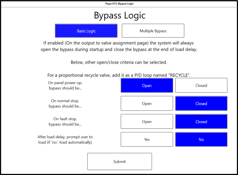
Once an output is assigned to run a bypass, in general the system will open the valve for startup and then close the valve when it is time to load the unit. The exact timings of both depend on a few other settings on the Bypass setup page under Brain -> Outputs Setup -> Bypass Logic.
Settings on this page:
- On panel power up, bypass should be...: Choose the state to have the bypass when the panel powers up
- On normal stop, bypass should be...: Choose the state for the bypass after a normal manual stop
- On fault stop, bypass should be...: Choose the state for the bypass after a fault shutdown
- After load delay, prompt user to load: If set to Yes, then after load delay a button appears in the corner telling the user the unit can be loaded. Selecting the button gives the option to close the bypass. If this setting is set to No, then the bypass will close automatically after load delay.
If the bypass is closed when the unit needs to be started then it will open during startup before pre-lube.
Note that if the bypass is set to close automatically after load delay (the last setting above is set to NO) then the process pressures should have low kills set to 'C' class to make sure the sequence doesn't fault out as the bypass is closing.
Multi bypass setup
The latest software versions for Dynamic Control panels added support to have multiple bypass valves on a panel that can be used for blowing down pressure from a unit to a header. This document describes how to use this feature.
The software versions required are the following or newer:
- DCT: 1.49.169
- Brain: 2200
Note: Earlier versions ran this sequence at shutdown, and was moved to startup with the above versions.
Specifying Inputs and Outputs
As mentioned in the overview, the Output to Valve Assignment page is used to specify which outputs and inputs are used for the bypass valves. There are three bypass valves that can be assigned:
- The first bypass "BYPASS" is from 1st suction to stage 2/3. This is the row used if there is only one bypass as well.
- The second bypass is for Stage 3 to 2.
- The last bypass is for an off-skid valve from the unit discharge to station header. It functions similar to a blowdown to release pressure from the unit, but to the header.
Not all three valves must be assigned- any combination can be used. Similarly, if valve feedback is not assigned then it will be ignored.
