Annunciator Valve Setup
The system can control a handful of on / off valves through digital outputs. Some aspects of the logic are covered on other pages, but the setup of the I/O is discussed here.
Output to Valve Assignment Screen
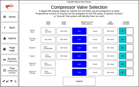
The ‘Output to Valve Assignment’ screen is used to set up the input/output pins used for basic on/off valves. This page is accessed by navigating to “Settings” -> “Brain” -> “Outputs Setup” -> “Output to Valve Selection”. The screen is shown below.
Note: Proportional valves for suction or recycle will not be set up here. This page is only used for valves that are either on or off.
For each valve, if it is used the output that drives the valve can be selected as Digital or Analog. To assign the output, select the box under digital or analog for the valve at that row.
The Open / Closed box on each row determine how the system knows if the valve will be open or closed when the output is on (or in the case of an analog output, at the maximum range).
- Open: The valve opens when the output turns on. Also known as ‘fail closed’, since off is closed.
- Closed: The valve closes when the output turns on. Also known as ‘fail open’, since off is open.
The Valve Feedback column can be used to assign a feedback to a valve – either digital or analog. To use, select the box for the valve and then use the subsequent page to pick the input(s) used for the feedback. Commonly, two digital inputs are used for open and closed limit switches.
Note: To change if a limit switch is normally open or closed, after completing setup on the valve setup page, go to digital input setup for that input and select normally open or closed.
The final column controls if the input is controlled by the system. Normally, this should be set to ON (blue). If set to OFF, the valve will only change on manual user command. This might be useful during initial setup for testing.
Note: Be sure to select ‘Submit’ on the final page when complete to save the settings!
Notes on Valve Feedback
When valve feedbacks are assigned to digital inputs the normally closed vs open can be switched in digital input setup in the same method as any digital input.
When a valve is commanded to a new state (by the digital output turning on / off) the valve is expected to meet the new feedback switch within a maximum amount of time. This time can be adjusted under Brain -> Misc Settings with the setting “Max Valve Change Time (s)”.
Other documentation for specific valves
- Blowdown: Annunciator Blowdown Setup
- Bypass: Annunciator Bypass Setup
Valve Gauges
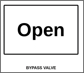
Each of the valves in the output to valve selection screen has an associated gauge that can be added to a home page slide. To do this, go to Settings -> Brain -> Gauges Setup, and select a relevant page. The gauge will show the current (intended) position of the valve.
Selecting the gauge shows the current output and input (if used) status. If in manual mode, selecting the gauge allows the user to open/close the valve.
Notes on Valve Testing
Generally, the easiest way to manually actuate valve is by going to the “Digital Output Testing” page under Brain -> “Output Status / Testing”. The unit must be stopped to use this screen. When reset is pressed the tests will clear.
Starting with DCT v1.49 there is a valve testing screen at Settings – Brain – Output Status / Testing – On/Off valve testing. This screen can be used to test valve outputs and inputs more conveniently than in other places.

