AFRC Map Setup
Note: This applies to the EIM only
The AFRC features the ability for the target setpoint to automatically adjust based on changes to environmental conditions or sensor readings. This is accomplished by building a table, or map, that associates multiple target setpoints to a set of sensor conditions. As the sensor readings change, an offset can be applied to the target setpoint so that it changes autonomously. This feature can be used to account for environmental factors or load swings that may affect the engine’s performance or emissions.
A map can contain as little as two, or as many as five, points. Each point includes an offset to the target setpoint and a sensor reading associated with that offset. The offset is a value that is applied to the original, or base, target setpoint displayed on the AFRC Home screen (Lite Pg. 300, Adv. Pg. 200). The sensor value can come from any of the available sensors that are mappable, but all points in the table must be associated with a single sensor.
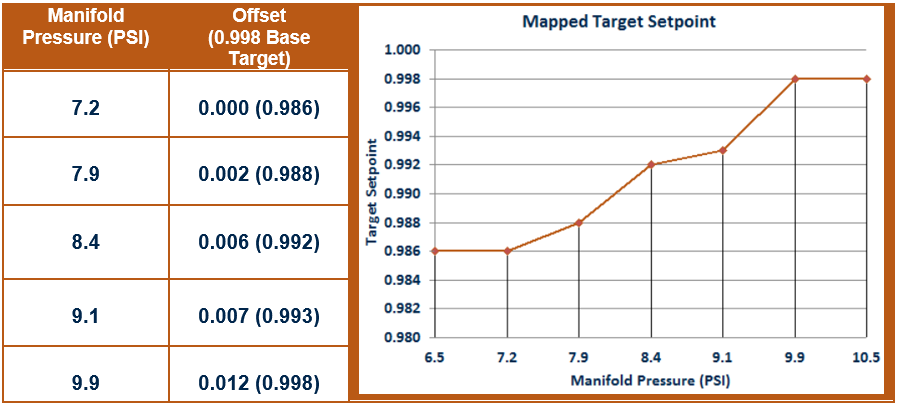
The generated target setpoint is calculated based on the two to five points entered within the table. If the sensor reading is between any two of the configured points within the table, the offset will be interpolated. If the sensor reading is less than the lowest value in the table, the corresponding lowest offset will be used. If the sensor reading is greater than the highest value in the table, the corresponding highest offset will be used.
Multi-Setpoint Graph Example
MAPPING SENSORS
While in “Setpoint” control mode, the AFRC Advanced provides the following sensor options for mapping while, if properly equipped:
- Manifold Pressure
- Ambient Temperature
- Manifold Temperature
- RPM
- Post-Catalyst O2
The AFRC Lite provides the following option for mapping, if properly equipped:
- Manifold Pressure
ADDING MAPPING POINTS
While in Engineering security mode, the Mapping Setup screen (Lite Pg. 330, Adv. Pg. 230) is available through the Setup screen (Lite Pg. 301, Adv. Pg. 201). This screen provides access to generating mapping points and enabling the mapping feature.
Before adding points to the mapping table, a sensor must be selected from the “Sensor” drop down box in the top center of the screen. The drop down box is populated based on sensors that are connected and enabled through any of the sensor setup screens. For the AFRC Lite, no drop down box is available as the only supported sensor is the manifold pressure sensor.
Upon selecting a sensor from the drop down box, the current sensor reading will be displayed within the “Create New Point” box on the mapping screen along with an offset of zero. If the engine emissions are currently satisfactory at current conditions, this condition can be added to the table by selecting any of the “Add” buttons within the “Mapping Table” box. The sensor value and associated offset of 0 will be added to the table.
Alternatively, the sensor value can be adjusted by selecting the “Increase” or “Decrease” buttons around the value. The offset associated with the selected sensor value can similarly be adjusted by pressing the “Rich” or “Lean” buttons around the displayed offset. When both the sensor and offset values are configured, select the “Add” button of the slot within the “Mapping Table” where the point is to be added.
The table is capable of accepting up to five (5) points but is valid with as few as two (2). Mapping points can be cleared out by selecting the associated “Delete” button next to the entry. The order of the points within the “Mapping Table” does not matter as the system will automatically sort the points based on the sensor value when the map is enabled. Points can only be added or deleted when the mapping feature is disabled.
RUNNING THE MAP
The toggle button in the upper left corner of the mapping screen must be selected to engage the mapping table. Enabling mapping will change the text to the right of the toggle button from “Mapping Off” to “Mapping On” and remove the buttons from the mapping table to make changes.
Below the toggle button is the status of the AFRC. Possible status messages include:
- “Attempting to Engage Mapping” – Mapping feature is being initialized
- “Mapping Active” – Mapping is currently operational
- “Mapping Not Enabled” – Mapping is off
- “AFRC Not Detected” – No AFRC was found when mapping attempting to initialize
- “Error – Check Setup” – An error occurred attempting to initialize mapping
- Not enough mapping points available
- Duplicate mapping points were present
