Annunciator Screw Compressor Loading
Overview
A screw compressor is a type of compressor that uses rotating 'screws' that continuously rotate and force air from larger to smaller air pockets. A capacity (or load) slide valve controls how much air is bypassed around the compressor, thus directly controlling load. Some compressors also have a "Vi" slider, which controls the ratio of air volume in the compressor from beginning to end of the load cycle. The annunciator can control the capacity slider, and optionally the Vi slider as well.
Screw compressor sliders are moved by energizing air solenoids that, while energized, force the slider to move one direction or another. Each slider will have two solenoids- one for each direction. If the annunciator is only controlling the load slider, then two outputs and solenoids are used (load/unload). If the annunciator is also controlling the Vi slider, than two additional outputs will be required for four total.
Optionally, the slider(s) may have a feedback sensor that gives the position of the slider as a 4-20 mA reading. The actual reading at each end stop is within the 4-20 range, but not necessarily 4 or 20 mA. This can be calibrated as described in the feedback section below.
The annunciator has the ability to load and unload a screw compressor based on sensor conditions. One - Four sensors can be used to control this loading. The sequence of operations is as follows:
- The annunciator enters normal engine running state with the screw loading in 'auto', OR after previously running in 'manual' the 'auto' mode is selected
- A load delay counts down
- The annunciator enters normal load / unload loop:
- If one or more sensors call for unload, the screw will be unloaded
- If the primary sensor calls for load and the other sensors are in deadband, the screw will be loaded
- Otherwise, the screw will not change
- Once enough pulses in a row have been sent, the annunciator will stop trying to move the load valve
The primary (first) sensor is the main sensor that controls loading and unloading. Which sensor is used will depend on field requirements. For example, if the unit can run fully loaded, then the primary load sensor can be manifold pressure, with other secondary sensors only for unloading in unsafe operating conditions (e.g. low suction). As another example, if a certain suction pressure needs to be maintained then the primary load sensor will be suction, and other secondary sensors can be used to trigger other minor unload conditions.
Setup
The screw load setup is reached from the annunciator home screen by selecting "Annunciator Setup" -> "Outputs Setup" -> "Screw Loading". The setup consists of two or three pages.
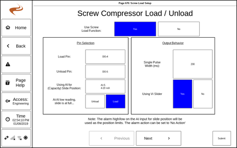
The first page is used to setup the following options:
- Use Screw Load Function: Select "Yes" to use
- Load Pin / Unload Pin: Select each box to pick a digital output to use for screw loading and unloading. These pins will be used to pulse the actuator each direction.
- Using AI for slide position: If the slide (capacity) position has a feedback, select the analog input here. Also select when the reading is low (e.g. 4 mA) the slide is at load or unload position.
- Single pulse width (ms): The width of one pulse. The longer the pulse, the more the slider will move for each loop cycle.
- Max Pulses: This specifies the number of pulses it takes to go from full open to full closed. This is only needed if not using AI for slide position.
- Using Vi Slider: If using a Vi slider that is controlled by the system, select 'Yes' here
If using a VI slider, then the next page will be VI setup. The items on the VI setup page are:
- Vi Increase Pin: Select to assign a digital output to control the Vi Increase solenoid
- Vi Decrease Pin: Select to assign a digital output to control the Vi Decrease solenoid
- Ai Input for Vi Feedback: Select the Analog input where the 4-20mA feedback from the slider is attached.
- Actual Vi at Low, High stop: Enter the values for the min and max Vi of the compressor.
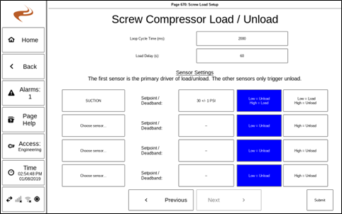
The final part of screw compressor load setup is shown below:
This page sets up actual control behavior. There are two global settings:
- Loop cycle time: This specifies the cycle time of the loop. A pulse will be sent this often while loading or unloading.
- Load delay: This specifies the amount of time after reaching BOTH running state and the load control selection in 'auto' when control will begin
The lower half of the page is for sensor settings. Up to four sensors can be selected, and at least one must be used.
The first sensor is the primary driver. If the other two sensors are in deadband or are not calling for unload, and the first sensor wants to load, the unit will load. If any sensor calls for unload, the unit will unload. The setting "Sensor Low = LOAD" vs "Sensor Low = UNLOAD" controls how an out of deadband reading is interpreted. If set to "Sensor Low = LOAD", then when the sensor reading is below the setpoint, it is considered a condition where the engine should be loaded. With this same setting, when the sensor is high (above the setpoint + deadband), the unit should be unloaded.
Note: If the manifold pressure is physically wired to a governor, ignition, or AFRC, the sensor can be used as a control option under the 'other' category. If the manifold pressure sensor is physically wired to the Brain, the sensor can be selected on the "Analog Inputs" category.
Screw Load Status
Once screw loading is enabled, the status information can be added to the home page in the place of a gauge. Gauge selection is under Gauges Setup. In the gauge selection dialog, the option "Screw Load Status" appears under the list for "other" items. Select this to add the status to a gauge set.
The screw load status page can be used to show the current status of the screw loading. On this page the load type can be switch between 'manual' and 'auto'. When in 'Manual', the user can manually send increase and decrease pulses. When in 'Auto' the system will load and unload the screw normally (after entering run and expiring the load delay). Note that pushing 'Manual Increase/Decrease Pulse' only causes a single pulse, and many pulses are required to move the slider very far. If Vi is used, the target button will be shown on this page. The button can be selected to select a new Vi value. When the unit is running at the control mode is 'Auto', the system will pulse the Vi increase/decrease solenoids to move the Vi slider to the target value.
Analog slide position feedback
Selecting the button "Slide Pos. / Calibration" on the screw status page will bring up the screw slide position page.
This page can be used to view the current position reading of the slider(s), and set the end stop. Each slider will show the current reading in both mA and scaled units. Note that the scaled unit reading won't be correct until the end stops are calibrated. To calibrate the end stops, move the sliders to their end stops either with the unit running or by using air connections when the unit is off. If in 'Engineering' access level, the 'Save XXX Stop' buttons can be used to save the current position of a slider as an end stop. This will cause the 4mA/20mA scaling values to be adjusted so that the readings show up correctly.
After calibrating, the capacity slide feedback input should be configured to add alarm limits to tell the Brain when to stop moving the slider. The system will stop loading or unloading when the input is alarmed (though the alarm action can be no action). For a common example, if the capacity slide is properly calibrated then the alarm limits for that input might be set to 15% and 95%, so that the capacity slider will stop pulsing right before the end stop. The alarm limits can be adjusted if different load ranges are desired, though this won't be common.
Example:
- Analog in 5 used for slide feedback
- Alarm Low: 20%
- Alarm High: 80 %
- Alarm Action: No Action
In the above setup, the system will load or unload the slide until the control is in deadband, or the slide reaches the edge of the range 20% - 80%, at which time the slide cannot move any further.
Control without feedback
If not using Analog Input for feedback, the system will pulse open or closed about the number of pulses specified as 'max pulses from open to closed'. Since there is no position feedback, the system will assume the slide is at the end position after that number of open or close pulses has been sent. Every 30 minutes the system will reset its assumed position in case the slide is drifting, and will start pulsing again.

