EDR to 20240 Connection
Background
The 20240 (EMD) is a module that historically has been used for ZZZZ compliance monitoring. Since it has a RS-485 slave port, it can also be used as a generic sensor to modbus translator.
In a typical scenario, a 20240 and a few sensors could be added to an old annunciator panel (e.g. TTD or DD-40) to allow the EDR to send the sensor values remotely.
The 20240 can be connected to the following number of sensors:
- Analog (e.g. pressure sensor): 5 - 7
- Thermocouple (Type K): 6
- Thermistor: 0 - 2
- Digital Inputs: 2
Note that the thermistor inputs can be used for thermistors or analog.
Wiring
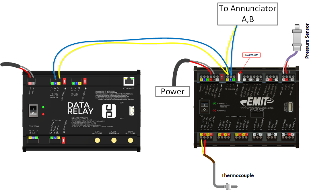
- Wire fused power into pins 4,5 of the 20240.
- For a typical loop powered pressure sensor, wire the power wire into a +12v pin (21, 17, 44) and the signal wire into the input (pin 20, 23, 45, 42, or 19).
- For thermocouples wire into pins 24-35 depending on input number
- For a digital input wire into 39 or 41 with the other side of the switch to ground (40)
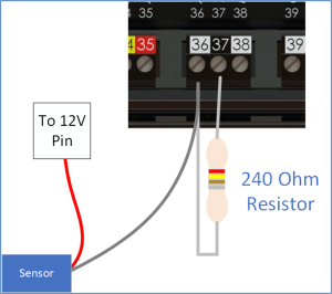
- For a thermistor wire between 36-37 or 38-37
- Wire the modbus A,B wire back to the EDR master port. In most cases the wires will then daisy-chain to the annunciator as shown in the diagram below. Since in this case wires are coming in and out of the 7,8,9 plug the termination switch will be off (in) as shown. In the less common case where the 20240 is at the end of the chain the termination will be on (out).
Input Numbering
The pins map to the input numbers with the following table.
| Input | Pin |
|---|---|
| Thermocouple 1 | 24, 25 |
| Thermocouple 2 | 26, 27 |
| Thermocouple 3 | 28, 29 |
| Thermocouple 4 | 30, 31 |
| Thermocouple 5 | 32, 33 |
| Thermocouple 6 | 34, 35 |
| Thermistor 1 | 36* |
| Thermistor 2 | 38* |
| Analog 1 | 20 |
| Analog 2 | 23 |
| Analog 3 | 45 |
| Analog 4 | 42 |
| Analog 5 | 19 |
| Analog 6 | 36* |
| Analog 7 | 38* |
| Digital in 1 | 39 |
| Digital in 2 | 41 |
- Pins 36 and 38 can be used as thermistor OR analog input (if adding a resistor), see below
Thermistor input note
Pins 36 and 38 can each be used as a thermistor or an analog input (but not both). Using as an analog input requires adding a 249 ohm resistor to ground. This would only be done if needing more than 5 analog inputs.
Configuring EDR
Once everything is wired up and powered, the EDR Modbus Master table can be altered to pull data from the EMD. See EDR_Wi-Fi_Console for information about connecting to the EDR Wi-Fi.
For each input in use, see 20240 EMD Modbus Table for the register number. The default ID for the EMD is "8", but this can be changed (see next section).
Example: If suction pressure sensor is wired to 20240 analog input 1 at pin 20, then the Suction pressure register on the EDR modbus table can be set to 30104 (and ID to 8 by default).
Scaling
Most registers have a special scaling as shown on the 20240 EMD Modbus Table. For thermocouples the offset and scale can be put into the EDR offset and scale to read the temperature properly. For analog inputs the offset and scale will map to a mA reading, so additional math will be required to actually translate to a proper pressure.
For sensors with a low range of 0, the offset will be -[sensor range / 4] , and the scale will be [sensor range / 1600]
Example : a 4-20mA input is used for a 0-300 psi sensor.
- Offset = -[300/4] = -75
- Scale = [300/1600] = 0.1875
Entering the offset and scale in the EMD row for that sensor will change the value to the proper pressure reading

