|
|
| (15 intermediate revisions by 2 users not shown) |
| Line 1: |
Line 1: |
| | See the bottom part of this page for a general overview, or the articles below for specific topics. |
| | |
| == Speed(Governor) Documents and Guide == | | == Speed(Governor) Documents and Guide == |
|
| |
|
| [[Modes Of Operation]] | | [[Speed Installation Guide]] |
|
| |
|
| [[Installation Guide]] | | [[Speed Home Screen]] |
|
| |
|
| [[Home Screen]] | | [[Speed Modes Of Operation]] |
|
| |
|
| [[Sensor Status Screen]] | | [[Speed Setup]] |
|
| |
|
| [[Setup]] | | [[Speed Sensor Status Screen]] |
|
| |
|
| [[Alarms]] | | [[Speed Alarms]] |
|
| |
|
| [[Sensor Setup]] | | [[Speed Sensor Setup]] |
|
| |
|
| [[Engineering Setup]] | | [[Speed Engineering Setup]] |
|
| |
|
| [[Throttle Calibration]] | | [[Speed Throttle Calibration]] |
|
| |
|
| [[Auto Override]] | | [[Speed Auto Override]] |
|
| |
|
| == Speed(Governor) Overview ==
| | [[Spare_Parts_Reference#Speed_(Governor)|Governor Parts]] |
| Video available for this topic: https://www.youtube.com/watch?v=wzNx_1Ptvis
| |
|
| |
|
| The EMIT Governor module is an electronic speed control system for stationary carbureted natural gas engines. The Governor system consists of two main components: the control board and an electronic throttle body. The control board is intended to be mounted in a panel or EIM enclosure. The throttle body comes in a variety of sizes for different engines, and mounts directly between the carburetor and intake manifold.
| | [[Throttle Types and Wiring]] |
|
| |
|
| The Governor works by monitoring the speed of the engine by reading a magnetic pickup (MPU) over the flywheel teeth. If the engine is running too slow or fast for the current control RPM, the throttle position is adjusted according to a PID control algorithm. The control speed is determined by a variety of conditions. First, the user can select through a panel switch one of three operating modes. They are “Idle,” “Manual,” or “Auto” speed control mode. In Idle mode, the Governor will hold the engine to an idle speed. In Manual mode, the user can increase or decrease the engine RPM, starting from the engine’s current speed, by using the “Speed+ / Speed-” switch on the panel. In Auto mode, the Governor control behavior will be determined in setup control mode, which may be configured to hold a fixed run speed or control to a certain compressor pressure.
| | == Speed(Governor) Overview == |
|
| |
|
| Pressure control under Auto mode, can either control to suction pressure or discharge pressure. In suction control mode, the speed decreases as suction pressure drops and increases as the pressure rises. This is intended for wells or situations where the intake pressure varies but the downstream system can handle the discharge pressure changes. In discharge control mode, by contrast, the engine will increase speed if discharge pressure is too low, and lower speed if discharge pressure is too high. This aims to keep the discharge pressure constant.
| | Video available for this topic: https://www.youtube.com/watch?v=wzNx_1Ptvis |
|
| |
|
| == Throttle Calibration ==
| | [[File:Speed rendering.jpg|400px]] |
| The Governor Throttle Calibration page (Pg. 523) can be used to re-calibrate the throttle body. This moves the throttle through its full range of motion and saves the values for the endpoints and also what effort is required to move the throttle. To get to this page, from the Governor Home Screen select "Setup" followed by "Throttle Calibration".
| |
|
| |
|
| The throttle will usually only need to be recalibrated if the throttle is changed. It could also help to recalibrate it if it seems the calibration is bad, such as if the throttle does not show “0%” with the engine is off. | | The EMIT Governor (Speed) module is an electronic speed control system for stationary carbureted natural gas engines. The Governor system consists of two main components: the control board and an electronic throttle body. The control board is intended to be mounted in a panel or EIM enclosure. The throttle body comes in a variety of sizes for different engines, and mounts directly between the carburetor and intake manifold. |
|
| |
|
| To calibrate, make sure the engine is off and click the “Calibrate Now” button. Wait for about 20 seconds for the calibration to complete.
| | The Governor works by monitoring the speed of the engine by reading a magnetic pickup (MPU) over the flywheel teeth. If the engine is running too slow or fast for the current control RPM, the throttle position is adjusted according to a PID control algorithm. The control speed is determined by a variety of conditions. First, the user can select through a panel switch one of three operating modes. They are “Idle,” “Manual,” or “Auto” speed control mode. In Idle mode, the Governor will hold the engine to an idle speed. In Manual mode, the user can increase or decrease the engine RPM, starting from the engine’s current speed, by using the “Speed+ / Speed-” switch on the panel. In Auto mode, the Governor control behavior will be determined in setup control mode, which may be configured to hold a fixed run speed or control to a certain compressor pressure. |
| | |
| == Auto Override ==
| |
| In some cases, it is useful to have the governor go to full speed during a pressure-control mode to anticipate an upcoming load change. The governor auto override allows for this.
| |
| | |
| In general, starting the override mode causes the governor to enter full speed for a given time period (e.g. 3 minutes). Once this time period expires, the governor returns to normal control mode.
| |
| | |
| The timer will start and count down regardless of control mode, but if the governor is not running in "Auto", the override timer will have no effect.
| |
| | |
| === Methods Of Triggering ===
| |
| The override mode can be triggered one of these ways:
| |
| | |
| # Modbus command: A write to modbus register 45107 at the governor address will cause the governor to start the override timer with the written value, in seconds. For example, if '60' is written to modbus register 45107, the governor will go to high 'auto' RPM for 60 seconds.
| |
| # CAN command: A command might come to the governor from another module triggering the override. This is set up from the module used.
| |
| # 'Discharge' input: The discharge pressure input can be configured to be used as the trigger to control the override mode. This is discussed in more detail below.
| |
| | |
| More than one of the above can be used at a time. For example, if the 'discharge' input is used to trigger an override period, a modbus command will still be accepted and will become the new timer value.
| |
| | |
| === Override Setup Page ===
| |
| The override setup page is accessed from the governor setup, then "Pressure-Control Override Setup". The page is shown below. | |
| | |
| <nowiki>*</nowiki>Insert Image*
| |
| | |
| The setting "Turn on 'Error Relay' output during override", if enabled, will cause the governor error relay to be on (closed to ground) whenever the override is active. This can be used to drive a lamp or to chain to another governor so that one master governor controls override on multiple units.
| |
| | |
| The next three options are related to the 'discharge' input trigger. This is discussed in the next section.
| |
| | |
| === Discharge Input Setup ===
| |
| The discharge input can be used to trigger the governor override. This can work in one of two ways
| |
| | |
| # Signal at discharge starts timer: In this mode, "Use Discharge input to control override" is set to YES, and "Hold override while discharge input active" is set to NO. In this configuration, when the discharge input becomes active (more than 6 mA) the 'default discharge time' starts counting down for the override period. For example, if setup as shown in the above screenshot, when the discharge input goes from below 6mA to above 6mA the governor will go to override mode (full speed) for three minutes, then the timer expires and the speed returns to normal.
| |
| # Hold override while discharge active: In this mode, both "Use Discharge input to control override" and "Hold override while discharge input active" are set to YES. This causes the governor to constantly override (go full speed) while the discharge input is above 6mA. As soon as the input goes below 6mA, the override ends. This is the only use of override mode where there is no timer involved.
| |
| | |
| Note: If discharge input is used for triggering override, it will always show up as "0" in the datalog and on the sensors screen to prevent false recordings.
| |
| | |
| === Wiring ===
| |
| One method for wiring the discharge input to be above 6mA is the following:
| |
| | |
| * Wire one end of a normally-open relay contact to the "+12V OUT" on the governor
| |
| * Wire the other end to a 1kOhm resistor
| |
| * Wire the other end of the resistor to the discharge input
| |
| * Wire the coil side of the relay to any control source
| |
| | |
| In this way, when the relay turns on, the discharge input becomes active. This example is shown below.
| |
|
| |
|
| <nowiki>*</nowiki>Insert Image*
| | Pressure control under Auto mode can either control to suction pressure or discharge pressure. In suction control mode the speed decreases as suction pressure drops and increases as the pressure rises. This is intended for wells or situations where the intake pressure varies but the downstream system can handle the discharge pressure changes. In discharge control mode, by contrast, the engine will increase speed if discharge pressure is too low, and lower speed if discharge pressure is too high. This aims to keep the discharge pressure constant. |
See the bottom part of this page for a general overview, or the articles below for specific topics.
Speed(Governor) Documents and Guide
Speed Installation Guide
Speed Home Screen
Speed Modes Of Operation
Speed Setup
Speed Sensor Status Screen
Speed Alarms
Speed Sensor Setup
Speed Engineering Setup
Speed Throttle Calibration
Speed Auto Override
Governor Parts
Throttle Types and Wiring
Speed(Governor) Overview
Video available for this topic: https://www.youtube.com/watch?v=wzNx_1Ptvis
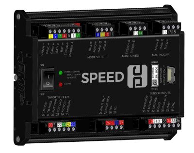
The EMIT Governor (Speed) module is an electronic speed control system for stationary carbureted natural gas engines. The Governor system consists of two main components: the control board and an electronic throttle body. The control board is intended to be mounted in a panel or EIM enclosure. The throttle body comes in a variety of sizes for different engines, and mounts directly between the carburetor and intake manifold.
The Governor works by monitoring the speed of the engine by reading a magnetic pickup (MPU) over the flywheel teeth. If the engine is running too slow or fast for the current control RPM, the throttle position is adjusted according to a PID control algorithm. The control speed is determined by a variety of conditions. First, the user can select through a panel switch one of three operating modes. They are “Idle,” “Manual,” or “Auto” speed control mode. In Idle mode, the Governor will hold the engine to an idle speed. In Manual mode, the user can increase or decrease the engine RPM, starting from the engine’s current speed, by using the “Speed+ / Speed-” switch on the panel. In Auto mode, the Governor control behavior will be determined in setup control mode, which may be configured to hold a fixed run speed or control to a certain compressor pressure.
Pressure control under Auto mode can either control to suction pressure or discharge pressure. In suction control mode the speed decreases as suction pressure drops and increases as the pressure rises. This is intended for wells or situations where the intake pressure varies but the downstream system can handle the discharge pressure changes. In discharge control mode, by contrast, the engine will increase speed if discharge pressure is too low, and lower speed if discharge pressure is too high. This aims to keep the discharge pressure constant.

