EDR Overview: Difference between revisions
| (11 intermediate revisions by the same user not shown) | |||
| Line 1: | Line 1: | ||
See the bottom part of this page for a general overview, or the articles below for specific topics. | |||
==EDR Documents and Guides== | ==EDR Documents and Guides== | ||
=== Main Guides === | |||
[[EDR Manual]] | [[EDR Manual]] | ||
| Line 5: | Line 9: | ||
[[EDR Wi-Fi Console]] | [[EDR Wi-Fi Console]] | ||
[[EDR | [[EDR Installation Guide]] | ||
[[EDR Troubleshooting Guide]] | |||
=== Minor Topics === | |||
[[Default Panel Settings for EDRs]] | |||
[[EDR Software Update]] | |||
[[EDR Field Configuration]] | [[EDR Field Configuration]] | ||
[[EDR | [[EDR Config Tool]] | ||
[[EDR Internal EDT Update]] | [[EDR Internal EDT Update]] | ||
[[EDR | [[Connecting EDR to EIM with Ethernet]] | ||
[[CAN Terminations With CAT Panel]] | |||
[[EDR Port Timings]] | |||
[[EDR to 20240 Connection]] | |||
[[EDR Loopback Test]] | |||
== EDR Overview == | |||
=== Hardware and System Overview === | |||
The EMIT Data Relay (EDR) is a module for interfacing non-EMIT control system data to EMIT’s telematics platform. Non-EMIT systems include popular compressor control annunciators and engine control units. The EDR connects to these systems via MODBUS and propriety protocols, organizes the data, and transmits the data via cellular modem to a customer facing database for remote observation. | |||
'''Power''' | |||
*12 – 30VDC power supply input range | |||
*Maximum power consumption: 30W | |||
'''Environmental''' | |||
*Temperature: -40°C to +65°C (-40°F to 149°F) T4 | |||
*Humidity: 5% - 90%, non-condensing | |||
'''Communication''' | |||
*USB host for future use | |||
*RS-485 half-duplex MODBUS RTU Master for panel annunciator communication | |||
*RS-485 half-duplex MODBUS RTU Slave for spare or expansion | |||
*Ethernet port for Modbus/TCP access, both master and slave | |||
*ECU J1708 and ECU CAN for Caterpillar ADEM access | |||
*Wi-Fi Antenna for local wireless access to unit information | |||
*Cell module for remote data collection and callouts | |||
*GPS for location service & accurate time | |||
=== General System Concepts === | |||
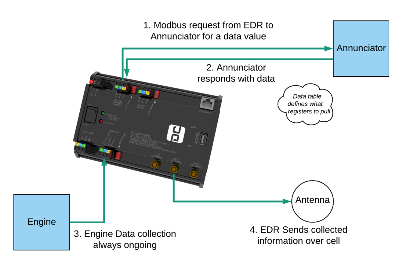
In the most typical use case, the Data Relay acts as a “Modbus Master” to a non-EMIT panel system. Using some defined data tables, the Data Relay will request data values such as suction pressure, oil temp, etc., from the panel system via RS-485 Modbus or Modbus/TCP. | |||
[[File:Edr-concept-diagram.png]] | |||
Each Modbus data value is configured by specifying a target Register and Slave ID of the source of the information (typically the panel annunciator). For example, the suction pressure might be present at Slave ID 10, Register 41001. The Data Relay will request for Register 41001 from Slave ID 10, the annunciator will respond with the data, and the Data Relay will store this response as “Suction Pressure”. | |||
This data is accumulated into standard blocks of information and then sent to EMIT Data Services via cell connection. This also includes run status information for the purposes of sending callouts. Additionally, the Data Relay will collect engine data from an engine control unit, such as Caterpillar ADEM ®, which will also be sent to the server. | |||
Separately, the Data Relay can operate as a Modbus Slave device. In this scenario, another SCADA system uses the Data Relay only for engine data translation. | |||
===Wiring=== | |||
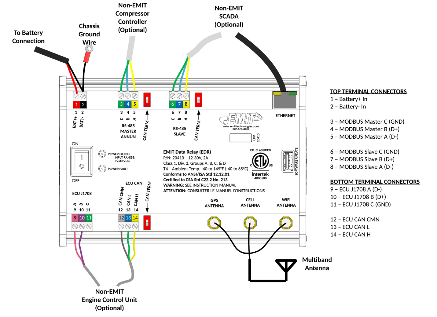
A general wiring diagram of all possible connections is shown below. In most cases some subset of these connections will be used. | |||
[[File:Edr-wiring-full.png]] | |||
===Configuration=== | |||
There are three spreadsheet files that define how an EDR communicates with another panel. These are called the modbus master table, the run status table, and the fault code (or shutdown code) table. | |||
These three files can be saved and loaded to different EDRs when the panels are the same. | |||
Creating a new configuration is described in the page [[EDR Field Configuration]] | |||
Additionally parts of the tables can be edited through the wifi console. See [[EDR Wi-Fi Console]] | |||
Latest revision as of 21:17, 5 January 2024
See the bottom part of this page for a general overview, or the articles below for specific topics.
EDR Documents and Guides
Main Guides
Minor Topics
Default Panel Settings for EDRs
Connecting EDR to EIM with Ethernet
CAN Terminations With CAT Panel
EDR Overview
Hardware and System Overview
The EMIT Data Relay (EDR) is a module for interfacing non-EMIT control system data to EMIT’s telematics platform. Non-EMIT systems include popular compressor control annunciators and engine control units. The EDR connects to these systems via MODBUS and propriety protocols, organizes the data, and transmits the data via cellular modem to a customer facing database for remote observation.
Power
- 12 – 30VDC power supply input range
- Maximum power consumption: 30W
Environmental
- Temperature: -40°C to +65°C (-40°F to 149°F) T4
- Humidity: 5% - 90%, non-condensing
Communication
- USB host for future use
- RS-485 half-duplex MODBUS RTU Master for panel annunciator communication
- RS-485 half-duplex MODBUS RTU Slave for spare or expansion
- Ethernet port for Modbus/TCP access, both master and slave
- ECU J1708 and ECU CAN for Caterpillar ADEM access
- Wi-Fi Antenna for local wireless access to unit information
- Cell module for remote data collection and callouts
- GPS for location service & accurate time
General System Concepts
In the most typical use case, the Data Relay acts as a “Modbus Master” to a non-EMIT panel system. Using some defined data tables, the Data Relay will request data values such as suction pressure, oil temp, etc., from the panel system via RS-485 Modbus or Modbus/TCP.
Each Modbus data value is configured by specifying a target Register and Slave ID of the source of the information (typically the panel annunciator). For example, the suction pressure might be present at Slave ID 10, Register 41001. The Data Relay will request for Register 41001 from Slave ID 10, the annunciator will respond with the data, and the Data Relay will store this response as “Suction Pressure”.
This data is accumulated into standard blocks of information and then sent to EMIT Data Services via cell connection. This also includes run status information for the purposes of sending callouts. Additionally, the Data Relay will collect engine data from an engine control unit, such as Caterpillar ADEM ®, which will also be sent to the server.
Separately, the Data Relay can operate as a Modbus Slave device. In this scenario, another SCADA system uses the Data Relay only for engine data translation.
Wiring
A general wiring diagram of all possible connections is shown below. In most cases some subset of these connections will be used.
Configuration
There are three spreadsheet files that define how an EDR communicates with another panel. These are called the modbus master table, the run status table, and the fault code (or shutdown code) table.
These three files can be saved and loaded to different EDRs when the panels are the same.
Creating a new configuration is described in the page EDR Field Configuration
Additionally parts of the tables can be edited through the wifi console. See EDR Wi-Fi Console

