|
|
| (19 intermediate revisions by 2 users not shown) |
| Line 1: |
Line 1: |
| | See the bottom part of this page for a general overview, or the articles below for specific topics. |
| ==AFRC Documents and Guides== | | ==AFRC Documents and Guides== |
|
| |
|
| [[Installation Guide]] | | [[AFRC Installation Guide]] |
|
| |
|
| [[Home Screen]] | | [[AFRC Home Screen]] |
|
| |
|
| [[Setup]] | | [[AFRC Setup]] |
|
| |
|
| [[Auto Control Range Alarm]] | | [[AFRC Controlling the Engine]] |
|
| |
|
| [[Engineering Adjustments]] | | [[AFRC Map Setup]] |
|
| |
|
| [[Map Setup]] | | [[Spare_Parts_Reference#AFRC|AFRC Parts]] |
|
| |
|
| [[Run Signal Trigger and System Temperature Units]] | | [[AFRC to EIM Wiring Diagrams]] |
|
| |
|
| == Overview == | | === Minor Topics === |
| The EMIT air/fuel ratio controller (AFRC) is available in two offerings: the AFRC Advanced and AFRC Lite. Both controllers are designed to control turbocharged or naturally aspirated carbureted stationary natural gas or propane engines for either rich-burn or lean-burn applications. The AFRC Advanced is equipped to control a dual or single-bank engine with multiple options available for sensory monitoring, multi-setpoint control, and an optional control algorithm, Auto Control. The AFRC Lite offers the same setpoint and multi-setpoint control as the AFRC Advanced but has been optimized for single-bank engines. Unless otherwise noted, both controllers will be referred to simply as “AFRC” through the remainder of the manual.
| |
|
| |
|
| Use of the AFRC controller with an appropriate catalytic converter can result in dramatic reductions in exhaust gas pollutants, particularly Oxides of Nitrogen (NOx), Carbon Monoxide (CO), and Hydrocarbons (HC). Rich-burn NSCR catalytic converters require a constant oxygen content of less than 0.5% from the engine in order to work effectively – the AFRC provides the control needed to maintain that constant oxygen concentration. In lean burn applications, the use of the AFRC with an oxidation catalyst can result in dramatic reductions in exhaust gas pollutants of Carbon Monoxide (CO), Hydrocarbons (HC) and Volatile Organic Compounds (VOC).
| | [[20360 O2 Heater Pin Issue]] |
|
| |
|
| The air fuel ratio of the engine is maintained by setting the appropriate oxygen sensor target setpoint that corresponds with the desired emissions reduction. The controller automatically targets and maintains the setpoint by adjusting the valve position which allows or restricts the amount gas streamed into the mixer which then richens or leans the engine. The valve is moved and stabilized using a finely-tuned Proportional Integral Derivative (PID) control loop that automatically adjusts the correct valve position quickly with little overshoot or error. If desired, multiple setpoints can be used to automatically change the target setpoint based on sensor readings through the AFRC’s mapping feature. In addition to this “Setpoint” control type, the AFRC Advanced offers optional “Auto Control” configuration for single bank or dual bank rich burn engines that can efficiently find and maintain the optimum target setpoint automatically for maximum emissions reduction. No setpoint adjustment or multi-setpoint mapping is required.
| | == Overview == |
|
| |
|
| == Mapping Setup ==
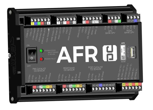
| | [[File:20230-AFRCA assembly ISO.jpg|500px]] |
| The AFRC features the ability for the target setpoint to automatically adjust based on changes to environmental conditions or sensor readings. This is accomplished by building a table, or map, that associates multiple target setpoints to a set of sensor conditions. As the sensor readings change, an offset can be applied to the target setpoint so that it changes autonomously. This feature can be used to account for environmental factors or load swings that may affect the engine’s performance or emissions.
| |
|
| |
|
| A map can contain as little as two, or as many as five, points. Each point includes an offset to the target setpoint and a sensor reading associated with that offset. The offset is a value that is applied to the original, or base, target setpoint displayed on the AFRC Home screen (Lite Pg. 300, Adv. Pg. 200). The sensor value can come from any of the available sensors that are mappable, but all points in the table must be associated with a single sensor.
| | The EMIT air/fuel ratio controller (AFRC) is available in several offerings: |
|
| |
|
| The generated target setpoint is calculated based on the two to five points entered within the table. If the sensor reading is between any two of the configured points within the table, the offset will be interpolated. If the sensor reading is less than the lowest value in the table, the corresponding lowest offset will be used. If the sensor reading is greater than the highest value in the table, the corresponding highest offset will be used.
| | {| class="wikitable" style="margin:auto" |
| | |+ AFRC Item Numbers |
| | |- |
| | ! Item Number !! Description !! Richburn (Narrowband) Banks !! Leanburn (Wideband) Banks |
| | |- |
| | | 20360 || AFRC-Single Richburn || 1 || 0 |
| | |- |
| | | 20235 || AFRC-Dual Richburn || 1 or 2 || 0 |
| | |- |
| | | 20230 || AFRC-Dual Rich or Leanburn || 1 or 2 || 1 or 2 |
| | |} |
|
| |
|
| <nowiki>*</nowiki>Insert Image*
| | All controllers are designed to control turbocharged or naturally aspirated carbureted stationary natural gas or propane engines for either rich-burn or lean-burn applications. The AFRC Advanced Dual is equipped to control a dual or single-bank engine with multiple options available for sensory monitoring, multi-setpoint control, and an optional control algorithm, Auto Control. The AFRC Advanced Single bank offers the same setpoint, multi-setpoint, and Auto control as the AFRC Advanced Dual but only covers single bank and narrowband applications. Unless otherwise noted, the controllers will be referred to simply as “AFRC” through the remainder of the manual. |
|
| |
|
| Multi-Setpoint Graph Example
| | Use of the AFR controller with an appropriate catalytic converter can result in dramatic reductions in exhaust gas pollutants, particularly Oxides of Nitrogen (NOx), Carbon Monoxide (CO), and Hydrocarbons (HC). Rich-burn NSCR catalytic converters require a constant oxygen content of less than 0.5% from the engine in order to work effectively – the AFRC provides the control needed to maintain that constant oxygen concentration. In lean burn applications, the use of the AFRC with an oxidation catalyst can result in dramatic reductions in exhaust gas pollutants of Carbon Monoxide (CO), Hydrocarbons (HC) and Volatile Organic Compounds (VOC). |
|
| |
|
| === MAPPING SENSORS ===
| | The air fuel ratio of the engine is maintained by setting the appropriate oxygen sensor target setpoint that corresponds with the desired emissions reduction. The controller automatically targets and maintains the setpoint by adjusting the valve position which allows or restricts the amount gas streamed into the mixer which then richens or leans the engine. The valve is moved and stabilized using a finely-tuned Proportional Integral Derivative (PID) control loop that automatically adjusts the correct valve position quickly with little overshoot or error. If desired, multiple setpoints can be used to automatically change the target setpoint based on sensor readings through the AFRC’s mapping feature. In addition to this “Setpoint” control type, the AFRC Advanced offers optional “Auto Control” configuration for single bank or dual bank rich burn engines that can efficiently find and maintain the optimum target setpoint automatically for maximum emissions reduction. No setpoint adjustment or multi-setpoint mapping is required. |
| While in “Setpoint” control mode, the AFRC Advanced provides the following sensor options for mapping while, if properly equipped:
| |
| | |
| * Manifold Pressure
| |
| * Ambient Temperature
| |
| * Manifold Temperature
| |
| * RPM
| |
| * Post-Catalyst O2
| |
| | |
| The AFRC Lite provides the following option for mapping, if properly equipped: | |
| | |
| * Manifold Pressure
| |
| | |
| === ADDING MAPPING POINTS ===
| |
| While in ''Engineering'' security mode, the Mapping Setup screen (Lite Pg. 330, Adv. Pg. 230) is available through the Setup screen (Lite Pg. 301, Adv. Pg. 201). This screen provides access to generating mapping points and enabling the mapping feature.
| |
| | |
| Before adding points to the mapping table, a sensor must be selected from the “Sensor” drop down box in the top center of the screen. The drop down box is populated based on sensors that are connected and enabled through any of the sensor setup screens. For the AFRC Lite, no drop down box is available as the only supported sensor is the manifold pressure sensor.
| |
| | |
| Upon selecting a sensor from the drop down box, the current sensor reading will be displayed within the “Create New Point” box on the mapping screen along with an offset of zero. If the engine emissions are currently satisfactory at current conditions, this condition can be added to the table by selecting any of the “Add” buttons within the “Mapping Table” box. The sensor value and associated offset of 0 will be added to the table.
| |
| | |
| Alternatively, the sensor value can be adjusted by selecting the “Increase” or “Decrease” buttons around the value. The offset associated with the selected sensor value can similarly be adjusted by pressing the “Rich” or “Lean” buttons around the displayed offset. When both the sensor and offset values are configured, select the “Add” button of the slot within the “Mapping Table” where the point is to be added.
| |
| | |
| The table is capable of accepting up to five (5) points but is valid with as few as two (2). Mapping points can be cleared out by selecting the associated “Delete” button next to the entry. The order of the points within the “Mapping Table” does not matter as the system will automatically sort the points based on the sensor value when the map is enabled. Points can only be added or deleted when the mapping feature is disabled. | |
| | |
| <nowiki>*</nowiki>Insert Image*
| |
| Mapping Setup Screen with Mapping Enabled
| |
| | |
| === RUNNING THE MAP ===
| |
| The toggle button in the upper left corner of the mapping screen must be selected to engage the mapping table. Enabling mapping will change the text to the right of the toggle button from “Mapping Off” to “Mapping On” and remove the buttons from the mapping table to make changes.
| |
| | |
| Below the toggle button is the status of the AFRC. Possible status messages include:
| |
| | |
| * “Attempting to Engage Mapping” – Mapping feature is being initialized
| |
| * “Mapping Active” – Mapping is currently operational
| |
| * “Mapping Not Enabled” – Mapping is off
| |
| * “AFRC Not Detected” – No AFRC was found when mapping attempting to initialize
| |
| * “Error – Check Setup” – An error occurred attempting to initialize mapping
| |
| * Not enough mapping points available
| |
| * Duplicate mapping points were present
| |
| | |
| == Run Signal Trigger and System Temperature Units ==
| |
| The run signal trigger and system temperature units are configured on the Run Signal Trigger screen (Pg. 10) of the EIM, which can be accessed under the AFRC Setup page (Pg. 201).
| |
| | |
| The AFRC uses one of seven possible methods to recognize if an engine is running. The available sensors to trigger the run signal are below.
| |
| | |
| * Auto-Detect (Default)
| |
| * Scans all other run-signal sources for conditions indicating the engine is running
| |
| * AFRC Pre-Catalyst Thermocouple
| |
| * AFRC Advanced terminals 48 and 49
| |
| * AFRC Lite terminals 21 and 22
| |
| * AFRC Oil Pressure Switch
| |
| * AFRC Advanced terminals 15 and 16
| |
| * Oil Pressure Switch must be enabled on Sensor Setup – AI/DI (Pg. 202) screen of the AFRC Advanced
| |
| * AFRC RPM
| |
| * AFRC Advanced terminals 17 and 18
| |
| * RPM must be enabled and pulses per revolution must be defined on Sensor Setup – RPM (Pg. 205) screen of the AFRC Advanced
| |
| * EMD Pre-Catalyst Thermocouple
| |
| * EMD terminals 24 and 25
| |
| * EMD Oil Pressure Switch
| |
| * EMD terminals 39 and 40
| |
| * Oil Pressure Switch must be enabled on Sensor Setup – AI/DI (Pg. 104) screen of the EMD
| |
| * Ignition State
| |
| * Uses the current ignition state to determine run signal, if the ignition is in the “Engine Running” or “Engine Running With Warnings” state the run signal is set to running.
| |
| | |
| “Auto-Detect” will scan the other enabled “Trigger Sensor” inputs of the AFRC Advanced, AFRC Lite, EMD, and Ignition and toggle the engine run signal to “Run” if any of them indicate the engine is running. | |
| | |
| If “Auto-Detect”, “AFRC Pre-Cat TC”, or “EMD Pre-Cat TC” is selected, a trigger temperature must also be configured. The trigger temperature defines the temperature at which the run signal will toggle. Any temperatures above the trigger will indicate the engine is running, and any temperatures below the trigger will indicate the engine is off. The default trigger temperature is 450°F.
| |
| | |
| Regardless of the selection on this screen, the ETS system will use “Auto-Detect” for the “Eng. Run” text on the top of pages, engine runtime hours, and alarm activation. The selection on the Run Signal Trigger page only effects when the AFRC considers the engine running. Note that if the AFRC pre-cat TC is the only sensor available, it will take time for the sensor to warm up enough for the EIM to display “Eng. Run”.
| |
| | |
| <nowiki>*</nowiki>Insert Image*
| |
See the bottom part of this page for a general overview, or the articles below for specific topics.
AFRC Documents and Guides
AFRC Installation Guide
AFRC Home Screen
AFRC Setup
AFRC Controlling the Engine
AFRC Map Setup
AFRC Parts
AFRC to EIM Wiring Diagrams
Minor Topics
20360 O2 Heater Pin Issue
Overview
The EMIT air/fuel ratio controller (AFRC) is available in several offerings:
AFRC Item Numbers
| Item Number |
Description |
Richburn (Narrowband) Banks |
Leanburn (Wideband) Banks
|
| 20360 |
AFRC-Single Richburn |
1 |
0
|
| 20235 |
AFRC-Dual Richburn |
1 or 2 |
0
|
| 20230 |
AFRC-Dual Rich or Leanburn |
1 or 2 |
1 or 2
|
All controllers are designed to control turbocharged or naturally aspirated carbureted stationary natural gas or propane engines for either rich-burn or lean-burn applications. The AFRC Advanced Dual is equipped to control a dual or single-bank engine with multiple options available for sensory monitoring, multi-setpoint control, and an optional control algorithm, Auto Control. The AFRC Advanced Single bank offers the same setpoint, multi-setpoint, and Auto control as the AFRC Advanced Dual but only covers single bank and narrowband applications. Unless otherwise noted, the controllers will be referred to simply as “AFRC” through the remainder of the manual.
Use of the AFR controller with an appropriate catalytic converter can result in dramatic reductions in exhaust gas pollutants, particularly Oxides of Nitrogen (NOx), Carbon Monoxide (CO), and Hydrocarbons (HC). Rich-burn NSCR catalytic converters require a constant oxygen content of less than 0.5% from the engine in order to work effectively – the AFRC provides the control needed to maintain that constant oxygen concentration. In lean burn applications, the use of the AFRC with an oxidation catalyst can result in dramatic reductions in exhaust gas pollutants of Carbon Monoxide (CO), Hydrocarbons (HC) and Volatile Organic Compounds (VOC).
The air fuel ratio of the engine is maintained by setting the appropriate oxygen sensor target setpoint that corresponds with the desired emissions reduction. The controller automatically targets and maintains the setpoint by adjusting the valve position which allows or restricts the amount gas streamed into the mixer which then richens or leans the engine. The valve is moved and stabilized using a finely-tuned Proportional Integral Derivative (PID) control loop that automatically adjusts the correct valve position quickly with little overshoot or error. If desired, multiple setpoints can be used to automatically change the target setpoint based on sensor readings through the AFRC’s mapping feature. In addition to this “Setpoint” control type, the AFRC Advanced offers optional “Auto Control” configuration for single bank or dual bank rich burn engines that can efficiently find and maintain the optimum target setpoint automatically for maximum emissions reduction. No setpoint adjustment or multi-setpoint mapping is required.

