|
|
| (27 intermediate revisions by 2 users not shown) |
| Line 1: |
Line 1: |
| == Overview ==
| | See the bottom part of this page for a general overview, or the articles below for specific topics. |
| The EMIT air/fuel ratio controller (AFRC) is available in two offerings: the AFRC Advanced and AFRC Lite. Both controllers are designed to control turbocharged or naturally aspirated carbureted stationary natural gas or propane engines for either rich-burn or lean-burn applications. The AFRC Advanced is equipped to control a dual or single-bank engine with multiple options available for sensory monitoring, multi-setpoint control, and an optional control algorithm, Auto Control. The AFRC Lite offers the same setpoint and multi-setpoint control as the AFRC Advanced but has been optimized for single-bank engines. Unless otherwise noted, both controllers will be referred to simply as “AFRC” through the remainder of the manual.
| | ==AFRC Documents and Guides== |
|
| |
|
| Use of the AFRC controller with an appropriate catalytic converter can result in dramatic reductions in exhaust gas pollutants, particularly Oxides of Nitrogen (NOx), Carbon Monoxide (CO), and Hydrocarbons (HC). Rich-burn NSCR catalytic converters require a constant oxygen content of less than 0.5% from the engine in order to work effectively – the AFRC provides the control needed to maintain that constant oxygen concentration. In lean burn applications, the use of the AFRC with an oxidation catalyst can result in dramatic reductions in exhaust gas pollutants of Carbon Monoxide (CO), Hydrocarbons (HC) and Volatile Organic Compounds (VOC).
| | [[AFRC Installation Guide]] |
|
| |
|
| The air fuel ratio of the engine is maintained by setting the appropriate oxygen sensor target setpoint that corresponds with the desired emissions reduction. The controller automatically targets and maintains the setpoint by adjusting the valve position which allows or restricts the amount gas streamed into the mixer which then richens or leans the engine. The valve is moved and stabilized using a finely-tuned Proportional Integral Derivative (PID) control loop that automatically adjusts the correct valve position quickly with little overshoot or error. If desired, multiple setpoints can be used to automatically change the target setpoint based on sensor readings through the AFRC’s mapping feature. In addition to this “Setpoint” control type, the AFRC Advanced offers optional “Auto Control” configuration for single bank or dual bank rich burn engines that can efficiently find and maintain the optimum target setpoint automatically for maximum emissions reduction. No setpoint adjustment or multi-setpoint mapping is required.
| | [[AFRC Home Screen]] |
|
| |
|
| == Installation Guide ==
| | [[AFRC Setup]] |
| The installation guide can be downloaded here: https://drive.google.com/open?id=1UkusWWJOSeBmjavjdAVOUHR_ocauA2Z1
| |
| The quick start guide can be downloaded here: https://drive.google.com/file/d/0BzOiNHLPWdg1UXlaX2YzOFM0dms/view?usp=sharing&resourcekey=0-c9itYJbFwTwDKjlhv3kEDg
| |
|
| |
|
| == Home Screen ==
| | [[AFRC Controlling the Engine]] |
| The AFRC Home screen provides all the necessary information and functionality to select the target setpoint, adjust the valve, enable/disable control, and access additional setup features. The left side of the screen is broken up into boxes which represent control for the individual banks of the engine. The right side of the screen provides a visual indication, through bar graphs, of the oxygen content of the exhaust, valve position, and catalyst temperatures. A security mode of Setup or Engineering is required to make any adjustments or changes to this screen.
| |
|
| |
|
| <nowiki>*</nowiki>Insert Image*
| | [[AFRC Map Setup]] |
|
| |
|
| AFRC Advanced or Lite Home Screen Shown In “Setpoint” Mode, Single Bank | | [[Spare_Parts_Reference#AFRC|AFRC Parts]] |
|
| |
|
| === CONTROL TOGGLE BUTTON (“Engaged” AND “Manual”) ===
| | [[AFRC to EIM Wiring Diagrams]] |
| Selecting the “Control:” toggle button in the upper right corner toggles the valve control mode of the AFRC between “Engaged” and “Manual”. The mode currently displayed within the button is the active mode.
| |
|
| |
|
| When the AFRC is in “Manual” mode:
| | === Minor Topics === |
|
| |
|
| * No control is active
| | [[20360 O2 Heater Pin Issue]] |
| * Target setpoint and valve position can be adjusted manually through the buttons available in the bank control boxes
| |
| * If the AFRC Advanced "Auto Control" mode is active, no target buttons are displayed
| |
| * When the AFRC is in “Engaged” mode:
| |
|
| |
|
| * The valve automatically adjusts to meet the target setpoint
| | == Overview == |
| * Target setpoint is free to be adjusted while in “Engaged” mode, but the valve position is not
| |
| * If the AFRC Advanced “Auto Control” mode is active, no target buttons are displayed
| |
|
| |
|
| === BANK CONTROL BOX ===
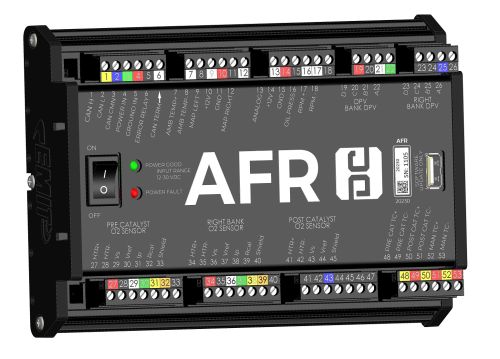
| | [[File:20230-AFRCA assembly ISO.jpg|500px]] |
| The control boxes for each bank contain the status of the control, target setpoint of the sensor, actual reading of the sensor, and valve position. The “Rich” and “Lean” buttons adjust the target setpoint accordingly, and the “Open” and “Shut” valves adjust the valve position accordingly. When the control is in “Auto” mode, the “Open” and “Shut” buttons are disabled as the controller automatically adjusts the valve position to match the actual sensor reading with the desired target setpoint. The target setpoint value can be adjusted in either “Auto” or “Manual” control mode.
| |
|
| |
|
| If the AFRC Advanced is in “Auto Control” mode, the “Lean” and “Rich” buttons are not displayed.
| | The EMIT air/fuel ratio controller (AFRC) is available in several offerings: |
|
| |
|
| <nowiki>*</nowiki>Insert Image*
| | {| class="wikitable" style="margin:auto" |
| | |+ AFRC Item Numbers |
| | |- |
| | ! Item Number !! Description !! Richburn (Narrowband) Banks !! Leanburn (Wideband) Banks |
| | |- |
| | | 20360 || AFRC-Single Richburn || 1 || 0 |
| | |- |
| | | 20235 || AFRC-Dual Richburn || 1 or 2 || 0 |
| | |- |
| | | 20230 || AFRC-Dual Rich or Leanburn || 1 or 2 || 1 or 2 |
| | |} |
|
| |
|
| Bank Control Box in “Setpoint” Mode
| | All controllers are designed to control turbocharged or naturally aspirated carbureted stationary natural gas or propane engines for either rich-burn or lean-burn applications. The AFRC Advanced Dual is equipped to control a dual or single-bank engine with multiple options available for sensory monitoring, multi-setpoint control, and an optional control algorithm, Auto Control. The AFRC Advanced Single bank offers the same setpoint, multi-setpoint, and Auto control as the AFRC Advanced Dual but only covers single bank and narrowband applications. Unless otherwise noted, the controllers will be referred to simply as “AFRC” through the remainder of the manual. |
|
| |
|
| <nowiki>*</nowiki>Insert Image*
| | Use of the AFR controller with an appropriate catalytic converter can result in dramatic reductions in exhaust gas pollutants, particularly Oxides of Nitrogen (NOx), Carbon Monoxide (CO), and Hydrocarbons (HC). Rich-burn NSCR catalytic converters require a constant oxygen content of less than 0.5% from the engine in order to work effectively – the AFRC provides the control needed to maintain that constant oxygen concentration. In lean burn applications, the use of the AFRC with an oxidation catalyst can result in dramatic reductions in exhaust gas pollutants of Carbon Monoxide (CO), Hydrocarbons (HC) and Volatile Organic Compounds (VOC). |
|
| |
|
| Bank Control Box in "AutoControl" Mode With No Setpoint Adjustment
| | The air fuel ratio of the engine is maintained by setting the appropriate oxygen sensor target setpoint that corresponds with the desired emissions reduction. The controller automatically targets and maintains the setpoint by adjusting the valve position which allows or restricts the amount gas streamed into the mixer which then richens or leans the engine. The valve is moved and stabilized using a finely-tuned Proportional Integral Derivative (PID) control loop that automatically adjusts the correct valve position quickly with little overshoot or error. If desired, multiple setpoints can be used to automatically change the target setpoint based on sensor readings through the AFRC’s mapping feature. In addition to this “Setpoint” control type, the AFRC Advanced offers optional “Auto Control” configuration for single bank or dual bank rich burn engines that can efficiently find and maintain the optimum target setpoint automatically for maximum emissions reduction. No setpoint adjustment or multi-setpoint mapping is required. |
| | |
| The status of the bank is displayed to the right of the bank label. The statuses of the banks are as follows:
| |
| | |
| * "No Run Signal" – No run signal is present or detected
| |
| * “Heater Warmup” – Run signal has been detected and the sensor heater is warming up to the operational temperature
| |
| * “Ready” – Sensor heater is warm and ready but control has not been enabled
| |
| * “Control Enabled, in Load Delay” – The load delay, defined on the Engineering Setup screen (Adv, Pg. 207/Lite Pg.306), is counting down before taking control
| |
| * “Attempting to Control” – Valve is actively adjusting to meet the desired target setpoint
| |
| * “Controlling” – The target setpoint has been met and control is stable
| |
| * “AutoControl is Active” – “Auto Control” control mode is currently engaged an operational
| |
| * “Failed Lean" – System is unable to maintain control and air fuel mixture is lean
| |
| * “Failed Rich” – System is unable to maintain control and air fuel mixture is rich
| |
| * “Invalid Readings” – Sensor values are outside the expected range
| |
| * “Heater Failure” – Sensor heater failed to warm up
| |
| * “AutoControl Startup State” – The AutoControl is in its startup state
| |
| * "Pre or Post Cat Over Temp" – One of the catalyst temperature readings are out of range
| |
| * "Waiting for exhaust to warm up" – The AFRCA is waiting for the exhaust to reach a minimum operating temperature (before moving to load delay)
| |
| | |
| === BAR GRAPHS ===
| |
| The “O2” bar graph displays the oxygen sensor readings in real time. Wideband sensors show richer values towards the bottom and leaner values towards the top. Narrowband sensors show richer values towards the top and leaner values towards the bottom. The graphs are labeled accordingly based on the sensor being used. Dual bank configurations will show two “O2” bar graphs, one for each bank, while a single bank configuration will only show a single bar graph. Red markers indicate the target setpoint of the bank.
| |
| | |
| The “Valve” bar graph displays the full range of the valve, 0 to 499, for each bank with the top being all the way open (499), and the bottom being all the way closed (0). Dual bank configurations will show two “Valve” bar graphs, one for each bank, while a single bank configuration will only show a single bar graph. A red bar over the valve bar graph(s) show the current home position(s). (AFRC software versions above 1444) | |
| | |
| The “Catalyst Temperature” bar graph displays the real-time readings for the pre-catalyst and post-catalyst thermocouples. Red markers indicate temperature alarm values configured.
| |
| | |
| === GRAPHS OF AFRC DATA OVER TIME ===
| |
| Any of the three bar graph areas on the AFRC Home screen can be selected to go to a short-term graph of the values along with some statistics. The "Go to Datalog" button can be selected to graph longer-term values of that input.
| |
| | |
| === VALVE HOMING ===
| |
| The AFRC valve(s) can be automatically or manually calibrated to a known “home” position. By default the home position is set at 249 steps, or in the middle of the valve range.
| |
| | |
| The AFRC home position can be either saved on "Manual" to "Engaged" control transition, or can be user-defined. To set how the home position is saved, select "Setup" on the home screen followed by "Valve Home Position(s)".
| |
| | |
| The value will automatically calibrate or home to these positions after the engine run signal toggles from “Run” to “Off”. Alternatively, the valves can be manually homed by selecting the “Home Valves” button while in Engineering security mode and in “Manual” control mode.
| |
| | |
| === SENSOR READINGS ===
| |
| The smaller box under the bar graphs display real-time readings of the catalyst thermocouples.
| |
| | |
| === BUTTONS ===
| |
| The “Sensors” button provides access to the Sensors screen (Lite Pg. 320, Adv. Pg. 220), which displays real-time readings for all the sensors that are connected to the AFRC and are enabled.
| |
| | |
| The “Setup” button provides access to additional configuration options for the AFRC including “Run Signal Trigger”, “Sensor Setup”, “Alarm Setup”, “Engineering Setup”, and “Mapping Setup”.
| |
| | |
| == Setup ==
| |
| Video available for this topic: https://www.youtube.com/watch?v=PAmjcq7CPt0
| |
| | |
| === ENGINE CONDITION ===
| |
| For proper AFRC operation, it is critical that the engine be in good operational status. Verify the following before running the AFRC:
| |
| | |
| * Valves are adjusted to factory specification
| |
| * Spark plugs are properly gapped and in good condition
| |
| * Cylinders have good compression
| |
| * Mixers are in good condition and regulator fuel pressure is set to factory specification
| |
| * Fuel connections are secure and leak-free
| |
| * Ignition system functioning correctly and timing set appropriately for fuel composition
| |
| *
| |
See the bottom part of this page for a general overview, or the articles below for specific topics.
AFRC Documents and Guides
AFRC Installation Guide
AFRC Home Screen
AFRC Setup
AFRC Controlling the Engine
AFRC Map Setup
AFRC Parts
AFRC to EIM Wiring Diagrams
Minor Topics
20360 O2 Heater Pin Issue
Overview
The EMIT air/fuel ratio controller (AFRC) is available in several offerings:
AFRC Item Numbers
| Item Number |
Description |
Richburn (Narrowband) Banks |
Leanburn (Wideband) Banks
|
| 20360 |
AFRC-Single Richburn |
1 |
0
|
| 20235 |
AFRC-Dual Richburn |
1 or 2 |
0
|
| 20230 |
AFRC-Dual Rich or Leanburn |
1 or 2 |
1 or 2
|
All controllers are designed to control turbocharged or naturally aspirated carbureted stationary natural gas or propane engines for either rich-burn or lean-burn applications. The AFRC Advanced Dual is equipped to control a dual or single-bank engine with multiple options available for sensory monitoring, multi-setpoint control, and an optional control algorithm, Auto Control. The AFRC Advanced Single bank offers the same setpoint, multi-setpoint, and Auto control as the AFRC Advanced Dual but only covers single bank and narrowband applications. Unless otherwise noted, the controllers will be referred to simply as “AFRC” through the remainder of the manual.
Use of the AFR controller with an appropriate catalytic converter can result in dramatic reductions in exhaust gas pollutants, particularly Oxides of Nitrogen (NOx), Carbon Monoxide (CO), and Hydrocarbons (HC). Rich-burn NSCR catalytic converters require a constant oxygen content of less than 0.5% from the engine in order to work effectively – the AFRC provides the control needed to maintain that constant oxygen concentration. In lean burn applications, the use of the AFRC with an oxidation catalyst can result in dramatic reductions in exhaust gas pollutants of Carbon Monoxide (CO), Hydrocarbons (HC) and Volatile Organic Compounds (VOC).
The air fuel ratio of the engine is maintained by setting the appropriate oxygen sensor target setpoint that corresponds with the desired emissions reduction. The controller automatically targets and maintains the setpoint by adjusting the valve position which allows or restricts the amount gas streamed into the mixer which then richens or leans the engine. The valve is moved and stabilized using a finely-tuned Proportional Integral Derivative (PID) control loop that automatically adjusts the correct valve position quickly with little overshoot or error. If desired, multiple setpoints can be used to automatically change the target setpoint based on sensor readings through the AFRC’s mapping feature. In addition to this “Setpoint” control type, the AFRC Advanced offers optional “Auto Control” configuration for single bank or dual bank rich burn engines that can efficiently find and maintain the optimum target setpoint automatically for maximum emissions reduction. No setpoint adjustment or multi-setpoint mapping is required.

