|
|
| (26 intermediate revisions by 2 users not shown) |
| Line 1: |
Line 1: |
| | See the bottom part of this page for a general overview, or the articles below for specific topics. |
| | |
| ==EIM Documents and Guides== | | ==EIM Documents and Guides== |
|
| |
|
| [[Timers]] | | ===Main Articles=== |
| | [[EIM User Interference]] |
| | |
| | [[EIM Timers]] |
| | |
| | [[EIM Alarms]] |
| | |
| | [[EIM Engine Information]] |
|
| |
|
| [[Alarms]] | | [[EIM Datalogging]] |
|
| |
|
| [[Engine Information]] | | [[EIM Config Files]] |
|
| |
|
| [[Modbus RTU]] | | [[EIM System Settings or Utilities Pages|EIM System Settings or Utilities Pages]] |
|
| |
|
| [[Custom Modbus Map]] | | [[EIM Software Update]] |
|
| |
|
| [[Datalogging]] | | [[EIM Notes Page]] |
|
| |
|
| [[System Settings / Utilities Pages]]
| | ===Minor Topics=== |
|
| |
|
| [[Software Update]] | | [[EIM Modbus RTU]] |
|
| |
|
| [[Notes Page]] | | [[EIM Custom Modbus Map]] |
|
| |
|
| [[Open Source Software Notice]] | | [[EIM Open Source Software Notice]] |
|
| |
|
| [[SD Or Boot Issues]] | | [[EIM SD Or Boot Issues]] |
|
| |
|
| [[Ethernet]] | | [[EIM Ethernet]] |
|
| |
|
| [[Security Key]] | | [[EIM Security Key]] |
|
| |
|
| [[Shutdown Logs]] | | [[Previous Shutdown Logs]] |
|
| |
|
| [[Modbus Temporary Disable]] | | [[EIM Modbus Temporary Disable]] |
|
| |
|
| == Overview == | | == Overview == |
| | |
| | [[File:20200-EIM.png]] |
| | |
| Video available for this topic: https://www.youtube.com/watch?v=GLwC7T6rGMQ | | Video available for this topic: https://www.youtube.com/watch?v=GLwC7T6rGMQ |
|
| |
|
| Line 40: |
Line 52: |
| The enclosure of the EIM was designed to be installed either externally using the faceplate and the base or within a panel using only the faceplate. If mounting externally, the EIM can accommodate the mounting of any one module within the base of the enclosure. | | The enclosure of the EIM was designed to be installed either externally using the faceplate and the base or within a panel using only the faceplate. If mounting externally, the EIM can accommodate the mounting of any one module within the base of the enclosure. |
|
| |
|
| === User Interface === | | === Specifications === |
| <nowiki>*</nowiki>Need to display visual*
| |
| | |
| === Display Contents And Operation ===
| |
| | |
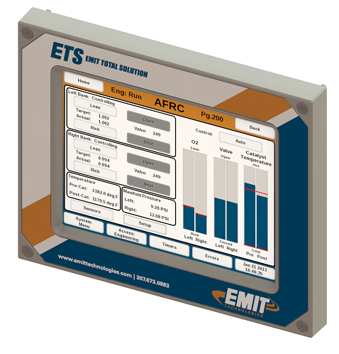
| ==== Header ====
| |
| * “Home” button – Navigates to home screen of currently viewed module
| |
| * “Eng” label – Indicates if valid run signal from the engine is present (“Eng: Run”) or not present (“Eng: Off”)
| |
| * Current module label – Displays the module associated with the currently viewed screen
| |
| * “Pg.” label – Displays page number associated with currently viewed screen
| |
| * “Back” button – Navigates to the previous screen
| |
| | |
| ==== Footer ====
| |
| * “System Menu” button – Navigates to System Menu screen (Pg. 0)
| |
| * “Access:” button – Displays current security access level and navigates to Security Access screen (Pg. 1) to change security level
| |
| * “Timers” button – Navigates to Timer Management screen (Pg. 20) and flashes when any timer(s) require attention
| |
| * “Alarms” button – Navigates to Alarms screen (Pg. 40) and flashes when there is an active alarm
| |
| * Date/Time button – Navigates to the Date/Time screen (Pg. 2) to modify the date and time
| |
| | |
| ==== Display Active Area ====
| |
| Displays content for the specific screen being viewed
| |
| | |
| === Security Access ===
| |
| The active security access is displayed in the “Access:” button in the footer of the display. To change the security access mode, select the “Access:” button and input the password of the desired security using the keypad. Available security levels include:
| |
| | |
| Operator – Limited access to system features. No adjustments can be made.
| |
| | |
| Setup – Access to most system features and settings.
| |
| | |
| Engineering – Access to all system features including advanced adjustments.
| |
| | |
| Passwords are laser marked on the USB covers included with each system, or on a paper card. Please contact EMIT Technologies if you have lost or forgotten the passwords.
| |
| | |
| === Changing Setup Password ===
| |
| To change the Setup password from the factory default (serial number + 10), do the following:
| |
| | |
| While in the Engineering security access mode, go to "System Settings / Utilities", and select "Change Setup Password".
| |
| | |
| Enter in the desired Setup password
| |
| | |
| Press the “Submit” button
| |
| | |
| == System Settings / Utilities Pages ==
| |
| The "System Settings / Utilities" Page, accessed from the EIM home screen, contains several back pages for system settings. A description of each is below, or a reference to another article if it exists.
| |
| | |
| <nowiki>*</nowiki>Insert Image*
| |
| | |
| === About ===
| |
| The About screen (Pg. 4) displays the serial number, hardware version, and software version of the EIM and each module connected to the EIM.
| |
| | |
| ==== Touchscreen Calibration ====
| |
| The touch screen can be re-calibrated if it is determined that button selection appears to be offset from what is displayed on the screen. To calibrate the touch screen:
| |
| | |
| * Enter Engineering security access mode
| |
| * Navigate to the About screen (Pg. 4)
| |
| * Select the “Calibrate Touch Screen” button to start the calibration application
| |
| * Very carefully, use quick motions to touch each crosshair as they appear on the screen
| |
| * After the calibration, the screen will return to the About screen (Pg. 4) and display a confirmation box that must be accepted
| |
| * If the confirmation box is not accepted, the touch screen will omit the new calibration data
| |
| | |
| For accuracy when selecting the crosshairs, it is recommended that you use a stylus, such as the blunt end of a pen, rather than using your finger.
| |
| | |
| Use caution not to double tap or select each crosshair as it will result in a bad calibration. The best method to not double tap is to select the crosshair in one quick motion.
| |
| | |
| === Go To Page ===
| |
| The "Go To Page" screen can be used to navigate to a page by the page number
| |
| | |
| === Software Update ===
| |
| The "Software Update" page is used to update the software on the EIM. To use, insert a USB drive with the software update into the EIM, and click "Start Update".
| |
| | |
| === Clean Screen ===
| |
| The "Clean Screen" page shows a blank screen so that the touch screen can be cleaned with a cloth without pressing any buttons.
| |
| | |
| === Main Help ===
| |
| The main help button goes to the help module of the EIM. This is the same as the "Help" button on the EIM home screen.
| |
| | |
| === MODBUS ===
| |
| The "Modbus" page is for setting up the Modbus connection. It is discussed more in-depth in the article "ETS Modbus RTU"
| |
|
| |
|
| === Config Files ===
| | '''Power''' |
| The "Config Files" page can be used to save or load settings from one EIM to another. To use, insert a USB drive and click "Write" for a module or all modules. Then take the USB drive to another unit and use the same screen "Read" button to read the settings and use them on the new unit. This can speed up setup times.
| |
|
| |
|
| === Reset ===
| | *12 – 30VDC power supply input range |
| In Engineering security mode, the system can be reset to the factory default values within the Reset screen (Pg. 5) of the EIM. Press the “Reset AFRC, EMD, EIM” button to reset those modules to factory defaults. Press the “Reset ICM” button to reset the Ignition to factory defaults. After reset the Ignition will be in “Configuration Required” state until ignition setup is completed.
| | *10 Watts maximum consumption |
|
| |
|
| === Datalog Files ===
| | '''Environmental''' |
| This page can be used to download or delete the datalog files. For more information, see the article "EIM Datalogging".
| |
|
| |
|
| === Home Background ===
| | *Temperature: -40°C to +65°C (-40°F to 149°F) |
| This page can be used to add a background watermark to the EIM home page.
| | *Humidity: 0% - 90%, non-condensing |
|
| |
|
| === Troubleshooting File ===
| | '''Communication''' |
| The EIM can accept a custom troubleshooting file for showing troubleshooting trees for certain shutdown conditions. This file will usually be supplied by EMIT and uploaded on this page.
| |
|
| |
|
| === Change Setup Password ===
| | *Controller Area Network (CAN) network for access to additional EMIT ETS modules |
| This page is used to change the setup password.
| | *USB host for datalog access and software updates |
| | *RS-485 half-duplex MODBUS RTU |
See the bottom part of this page for a general overview, or the articles below for specific topics.
EIM Documents and Guides
Main Articles
EIM User Interference
EIM Timers
EIM Alarms
EIM Engine Information
EIM Datalogging
EIM Config Files
EIM System Settings or Utilities Pages
EIM Software Update
EIM Notes Page
Minor Topics
EIM Modbus RTU
EIM Custom Modbus Map
EIM Open Source Software Notice
EIM SD Or Boot Issues
EIM Ethernet
EIM Security Key
Previous Shutdown Logs
EIM Modbus Temporary Disable
Overview
Video available for this topic: https://www.youtube.com/watch?v=GLwC7T6rGMQ
The EMIT Interface Module (EIM) provides an 8” touchscreen display and communication hub for any one module, or multiple modules, connected to the Controller Area Network (CAN) of the EIM. Modules connected to the EIM will automatically populate as buttons on the System Menu screen (Pg. 0) of the display. Selecting any of the module buttons allows for direct interaction with the respective module.
Other functions not directly related to module interaction include the system run signal trigger, security passwords and access, timer management, alarms, date and time, sensor data logging, and MODBUS communications.
The enclosure of the EIM was designed to be installed either externally using the faceplate and the base or within a panel using only the faceplate. If mounting externally, the EIM can accommodate the mounting of any one module within the base of the enclosure.
Specifications
Power
- 12 – 30VDC power supply input range
- 10 Watts maximum consumption
Environmental
- Temperature: -40°C to +65°C (-40°F to 149°F)
- Humidity: 0% - 90%, non-condensing
Communication
- Controller Area Network (CAN) network for access to additional EMIT ETS modules
- USB host for datalog access and software updates
- RS-485 half-duplex MODBUS RTU

